

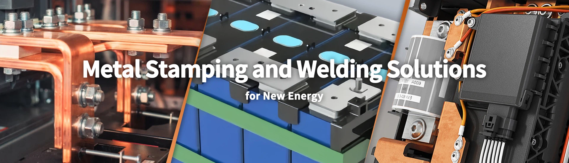
Custom Fuse Holder Manufacturer for EV, PV, and NH Fuse Applications
Xiamen Apollo Stamping Welding Technology manufactures custom fuse holders and electrical fuse bases for EV, PV, NH, and industrial power distribution systems. Our production covers T2Y2 copper terminals, CuSn6 bronze contact components, 65Mn spring clips, and metal-to-ceramic assemblies. In-house stamping, tooling and joining processes support repeatable component production for electrical fuse installations.
Apollo supports OEM fuse holder projects through drawing review, DFM assessment, material selection and tooling development. Critical dimensions, contact geometry, spring characteristics, and plating requirements are evaluated against customer specifications. Inspection plans and PPAP Level 3 documentation can be arranged for qualified automotive projects, with production records supporting batch traceability and repeat orders.
Request a Factory Direct Fuse Holder Quote
Explore Our Fuse Holder Product Catalog
Browse copper fuse bases, NH fuse holders, spring clip holders, and ceramic assemblies for different fuse mounting and electrical connection requirements.
-
![Copper Bases For Knife Type NH Fuse Links]()
Copper Bases For Knife Type NH Fuse Links
Add to Inquiry -
![Fuse Clip Holder]() Add to Inquiry
-
![Spring Clip Fuse Holder]() Add to Inquiry
-
![Copper Nickel Plated Fuse Base]()
Copper Nickel Plated Fuse Base
Add to Inquiry -
![NH Fuse Base]() Add to Inquiry
-
![Holder Fuse]() Add to Inquiry
-
![Fuse Holder For Glass Fuse]() Add to Inquiry
-
![NH Fuse Bases]() Add to Inquiry
-
![Fuse Clamp]() Add to Inquiry
-
![Fuse Blocks Holder]() Add to Inquiry
-
![Blade Contact For Ceramic Fuse Base]()
Blade Contact For Ceramic Fuse Base
Add to Inquiry -
![NH Series Fuse Base Knife Contact]()
NH Series Fuse Base Knife Contact
Add to Inquiry

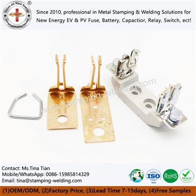


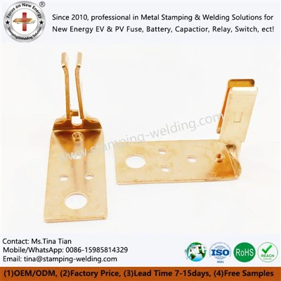
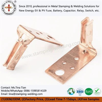


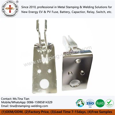
Material Standards, Tooling & Forming Processes
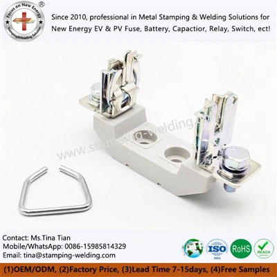
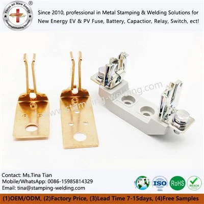
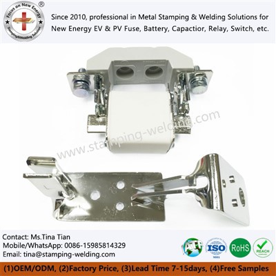
A fuse holder must maintain the specified mounting geometry and provide a stable interface with the corresponding fuse. The required material depends on whether the component primarily serves as a conductive base, a spring contact, a mounting support, or a combination of these functions.
Copper and Brass Material Selection
Apollo's published fuse holder range includes T2Y2 copper components and H65 brass components. The company also lists copper holders manufactured from 2.5 mm T2 copper sheet for selected base-contact designs. These are product-specific examples, not universal specifications for every fuse holder.
Copper offers high electrical conductivity and is suitable for current-carrying bases and contacts. Brass can provide a different balance of conductivity, strength, and formability, making it suitable for selected formed components. Final material selection should follow the current rating, mechanical loading, contact design, and customer drawing.
Precision Stamping and Forming
Fuse holder components may require several operations to achieve the final shape:
Progressive die stamping: Produces repeatable punched profiles, slots, and mounting features in suitable high-volume designs.
Bending and forming: Establishes contact geometry and the position of the conductive interface.
Tapping and threading: Provides mounting or fastening features where specified.
Riveting and joining: Integrates separate conductive parts when the design requires an assembled structure.
Tooling compensation: Accounts for material thickness, springback, and dimensional changes during forming.
For knife-type fuse holders, the width of the contact slot, contact alignment, and clamping geometry should be treated as critical-to-quality characteristics when identified by the drawing. Tool wear and material variation must also be considered when defining inspection frequency.
Fuse Holder Specifications Table
| Parameter | Specification basis | Recommended verification |
| Conductive material | T2/T2Y2 copper or approved copper alloy | Material certificate and grade verification |
| Formed components | H65 brass or drawing-specified alloy | Material certificate and dimensional inspection |
| Material thickness | Defined for each holder design | Micrometer or thickness gauge |
| Mounting dimensions | Customer drawing and applicable fuse interface | Optical measurement, CMM, or calibrated gauges |
| Contact geometry | Slot width, contact alignment, and seating dimensions | Go/no-go gauges and dimensional measurement |
| Surface treatment | Tin, nickel, or silver plating as specified | Coating thickness and visual inspection |
| Joining method | Riveting, resistance welding, brazing, or another approved method | Joint inspection and specified mechanical tests |
| Electrical performance | Rated current and temperature-rise requirements of the intended assembly | Resistance and temperature-rise testing under defined conditions |
All tolerances and acceptance limits should be agreed upon before production. A tolerance of ±0.01 mm should only be applied to dimensions for which the part design, manufacturing process, and measurement method support that requirement.
For a specific NH fuse holder design, review the NH Fuse Holder product page.
Advanced Joining, Electrical Contacts & Surface Treatments
Fuse holder performance depends on the electrical interface between the holder and the fuse. Contact geometry, surface condition, clamping force, and material selection affect contact resistance. A holder that fits mechanically but does not maintain the required contact pressure may develop unstable resistance and localized heating during service.
Joining Processes for Conductive Holder Assemblies
Where a holder consists of multiple metal components, the joining process should be selected according to the joint geometry, material combination, and electrical load.
Resistance welding: Suitable for specified metal joints where electrode force, current, and weld duration can be controlled.
Riveting: Mechanically joins separate components where the design requires a fixed connection.
Tin soldering or silver brazing: Used where the specified materials, joint clearance, and operating conditions support the process.
Laser welding: An option for compatible joint geometries requiring localized heat input.
Joining validation should address joint continuity, mechanical retention and electrical resistance. Visual inspection alone cannot confirm that a joint meets the required electrical or mechanical acceptance criteria.
Surface Treatment Selection
Tin, nickel, and silver plating serve different purposes. The appropriate coating depends on the base material, contact interface, environmental exposure, and electrical requirements.
| Surface treatment | Selection considerations | Inspection focus |
| Tin plating | Contact interface and corrosion requirements | Coating thickness, coverage and surface condition |
| Nickel plating | Specified barrier or surface protection requirements | Coating thickness, adhesion and coverage |
| Silver plating | Applications requiring a specified silver contact surface | Coating thickness, surface condition and contact resistance |
| Ultrasonic cleaning | Removal of processing residues before subsequent operations or packing | Cleanliness and residue control |
Plating thickness must be defined by the approved drawing or coating specification. A range such as 3–10 μm should not be applied indiscriminately to all holder surfaces; the required thickness depends on the coating system, substrate, and intended contact function.
For selected copper holder designs, Apollo lists nickel plating as a surface treatment option. See the Copper Nickel-Plated Fuse Base page for the relevant product configuration.
Electrical and Mechanical Validation
For a custom fuse holder project, the validation plan should define:
Contact resistance measured at the specified test current and connection points.
Temperature rise at the rated operating current under agreed ambient conditions.
Contact retention and mechanical strength where the interface is subject to insertion, removal, or vibration.
Coating thickness and coverage at the functional contact area.
Dimensional compatibility with the designated fuse and mounting system.
Environmental exposure requirements where humidity, corrosion, or temperature cycling is relevant.
The electrical rating of a complete fuse holder assembly must be established through the applicable design and qualification process. Material selection or plating alone does not establish an assembly's rated current, voltage, or short-circuit performance.
Quality Control & Certifications at Apollo
Fuse holder quality control should focus on fit, contact geometry, electrical performance, and repeatability across production lots. The inspection plan should identify critical dimensions, material requirements, surface treatment, joining characteristics, and the evidence required for product release.
Incoming Material and Dimensional Inspection
Incoming copper and brass materials should be verified against the approved grade and thickness specification. During stamping and forming, inspection should focus on slot width, mounting holes, bend angles, flatness, burrs, and contact alignment where these characteristics affect assembly.
Optical measurement systems, CMM equipment, and calibrated gauges may be assigned according to part geometry and required measurement uncertainty. Inspection methods should be capable of verifying the drawing tolerance rather than relying on a generic equipment accuracy figure.
Electrical and Assembly Testing
For conductive fuse holders, the inspection plan may include:
Contact resistance measurement at defined test points.
Temperature-rise testing under specified current and ambient conditions.
Mechanical retention or pull-off testing where relevant to the joint design.
Plating thickness and surface coverage inspection.
Dimensional checks against the designated fuse interface.
Visual inspection for cracks, deformation, burrs, and joining defects.
Test reports should state the sample identification, test conditions, measurement method, and acceptance limits. A test result without these details may not be sufficient for comparing different production lots.
Quality Documentation and Traceability
Apollo identifies ISO 9001 and IATF 16949 among the quality credentials presented on its website. Applicable certification scope and current status should be confirmed for the project before they are referenced in a customer approval package.
For automotive programs requiring PPAP Level 3, the documentation scope can be agreed with the customer and may include:
Process flow diagram.
Process Failure Mode and Effects Analysis (PFMEA).
Control plan.
Material certificates.
Dimensional inspection results.
Measurement system or process capability evidence where required.
Approved samples and applicable submission records.
The final package must reflect the actual production process and the customer's submission requirements. CPK values should be supported by relevant process data rather than stated as a blanket guarantee.
Packaging and Batch Control
Packaging should prevent bending, surface damage, and contamination of contact interfaces during storage and transportation. For repeat orders, lot identification should link finished components to the relevant material batch and production records. Packing quantity, protective materials, labels, and shipping configuration should be agreed before dispatch.
Frequently Asked Questions
Q: 1. What materials are available for custom fuse holders?
A: Apollo's published range includes T2Y2 copper fuse holders and copper or brass components for selected fuse base designs. The appropriate grade depends on electrical conductivity, forming requirements, contact force, and corrosion exposure. Submit the drawing and operating conditions to establish the correct material specification.
Q: 2. Can Apollo manufacture NH knife-type fuse holders to customer drawings?
A: Apollo lists NH fuse holders and knife-type fuse bases in its product range. Custom assessment should cover fuse interface dimensions, contact slot geometry, mounting holes, material thickness, and surface treatment. The designated fuse model and installation drawing help establish compatibility before tooling or production approval.
Q: 3. How can contact resistance and temperature rise be controlled?
A: Control requires stable contact geometry, suitable material, consistent contact pressure, and an appropriate surface finish. Resistance and temperature-rise testing should use defined current, ambient conditions, and measurement points. Acceptance limits must correspond to the intended assembly rating and the customer's applicable qualification requirements.
Q: 4. Which plating should be specified for a copper fuse holder?
A: Tin, nickel, and silver plating should be selected according to the contact interface, corrosion exposure, and electrical requirements. The drawing should specify coating type, minimum thickness, measurement locations, and applicable inspection methods. Where repeated insertion or vibration occurs, contact stability should be evaluated under representative service conditions.
Request a Custom Fuse Holder Quote
A reliable fuse holder starts with a defined fuse interface, verified material specification, and measurable acceptance criteria. Send your drawing to Apollo for a manufacturing review covering forming feasibility, mounting dimensions, conductive contact geometry, and surface treatment.
Please provide your 2D drawing in .DWG or PDF format, your 3D model in STEP format where available, the designated fuse model, material and plating requirements, expected annual volume, and applicable electrical ratings.
For new projects, the review can identify critical dimensions, proposed manufacturing processes, and required inspection records before tooling approval. A preliminary DFM review and quotation within 24 hours may be arranged for complete inquiries, subject to drawing complexity and engineering workload.
We're well-known as one of the leading fuse holder manufacturers and suppliers in China. Please feel free to buy high quality fuse holder at competitive price from our factory. For more information, contact us now.
Fuse Copper Knife, Fuse Copper T2Y2 Bases, Fuse Copper T2Y2 Holders