

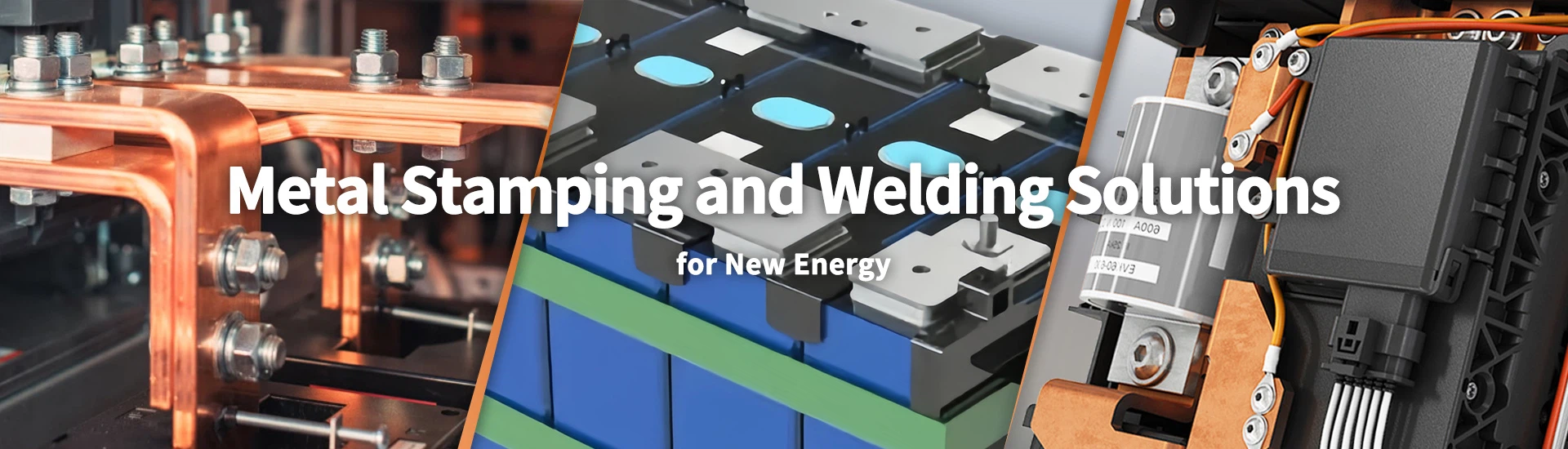
Fuse Cap and Contact Manufacturer for EV, PV, and High-Voltage Fuse Applications
Xiamen Apollo Stamping Welding Technology manufactures copper fuse caps, brass inner caps, fuse contacts, and terminal assemblies for EV, PV, NH, and high-voltage fuse applications.
Main product materials and manufacturing capabilities:
Copper: T2Y2 / C1100 copper for conductive caps and terminals.
Brass: H65 brass for formed inner caps and mechanical components.
Forming: Progressive die stamping, deep drawing, and precision punching.
Joining: Resistance welding, tin soldering, and silver brazing.
Finishing: Tin, silver, and nickel plating according to drawings.
For OEM production, Apollo supports drawing review, DFM assessment, tooling development and batch inspection. Critical dimensions, plating thickness, joint requirements, and PPAP Level 3 documentation are defined according to project specifications.
Request a Factory Direct Quote
Explore Our Fuse Cap and Contact Product Catalog
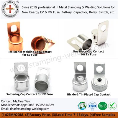
Browse copper fuse caps, brass inner caps, knife contacts, fast fuse terminals, and fuse holders for different electrical protection assemblies.
-
![Fuse Inner Outer Cap]() Add to Inquiry
-
![Fuse Cap Contact Assembly]() Add to Inquiry
-
![Fuse Knife Contacts]() Add to Inquiry
-
![Brass Inner Caps For EV Fuse]() Add to Inquiry
-
![Brass Inner Caps For PV Fuse]() Add to Inquiry
-
![Copper Outer Cap For Eaton Bussmann Fuse]()
Copper Outer Cap For Eaton Bussmann Fuse
Add to Inquiry -
![Copper Cap For Bussmann Series Class H(K) Fuses]()
Copper Cap For Bussmann Series Class H(K) Fuses
Add to Inquiry -
![Electrical Fuse Contact]() Add to Inquiry
-
![Fuse Cap And Contact Tin Welding]()
Fuse Cap And Contact Tin Welding
Add to Inquiry -
![Blade Fuse Terminal]() Add to Inquiry
-
![Copper Bases For Knife Type NH Fuse Links]()
Copper Bases For Knife Type NH Fuse Links
Add to Inquiry -
![Round Shape Copper End Cap]() Add to Inquiry



Material Standards, Tooling & Forming Processes
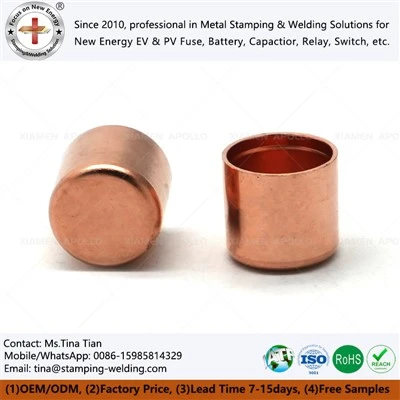
Fuse caps and contacts must meet both mechanical and electrical requirements. Copper grades such as T2 may be specified for conductive parts, while brass grades may be selected for formed caps and inner components where stiffness, machinability, and shape retention are relevant. Final selection depends on the drawing, operating current, temperature range, and joining process.
Progressive die stamping supports repeatable production of high-volume contact profiles. Deep drawing can form cap geometries, while secondary punching and trimming establish mounting features and finished edges. Die design must account for material thickness, temper, forming radius, springback, and burr orientation. These factors influence assembly fit and the consistency of the electrical contact interface.
For complex parts, the DFM review should identify critical dimensions, datum references, forming risks and inspection methods before tooling manufacture. A tolerance of ±0.01 mm should only be specified where the geometry, material, process capability and measurement method support it.
Fuse Cap and Contact Specifications
| Parameter | Specification basis | Inspection method |
| Conductive material | T2 copper or customer-specified copper grade | Material certificate review |
| Inner cap material | Specified brass grade or copper alloy | Material identification and dimensional inspection |
| Material thickness | Drawing-defined | Calibrated thickness gauge |
| Critical dimensions | Customer drawing and approved tolerances | Optical measurement, CMM, or gauges |
| Formed profile | Cap depth, wall condition, and geometry | Visual and dimensional inspection |
| Edge quality | Burr direction and edge condition per drawing | Visual inspection and specified gauging |
| Surface treatment | Tin, nickel, or silver plating where specified | Coating specification and thickness measurement |
| Joining | Resistance welding, soldering, or silver brazing as applicable | Visual, electrical, and mechanical tests |
Tooling and Production Controls
Forming quality: Monitor cracking, wrinkling, and wall thinning in drawn caps.
Dimensional stability: Verify critical dimensions during first-article approval and production.
Burr management: Control cutting edges and burr orientation to protect assembly fit and contact surfaces.
Tool wear: Establish inspection intervals based on tooling condition and production volume.
Traceability: Link material lots and process records to the finished-part batch.
For component-specific geometry and assembly configurations, review Fuse Cap Contact Assembly.
Advanced Joining, Insulation & Surface Treatments
The joining process affects the electrical path, mechanical retention and thermal behavior of a fuse contact assembly. Resistance welding, tin soldering and silver brazing may be selected according to material compatibility, joint geometry, production volume and customer specifications.
Resistance welding requires control of current, electrode force, weld duration and electrode condition. For soldered or brazed joints, surface cleanliness, joint clearance, filler material and heating conditions influence wetting and joint consistency. Process qualification should define the required electrical resistance, mechanical strength, and inspection method rather than relying on visual appearance alone.
Plating Requirements for Electrical Contacts
Tin, nickel and silver plating provide different surface properties. Selection should reflect the mating material, operating environment, contact force, temperature exposure, and applicable electrical requirements.
A production drawing should specify:
Plating type and any required underlayer.
Minimum coating thickness and measurement locations.
Acceptable surface defects and exposed substrate limits.
Contact resistance acceptance criteria where applicable.
Environmental and mechanical qualification requirements.
A nominal coating thickness of 3–10 μm may be considered for certain designs, but it should not be treated as a universal requirement for all fuse caps and contacts. The final thickness must follow the drawing and validated product specification.
Where vibration or repeated contact movement is expected, qualification should assess the actual interface for resistance changes, wear, and corrosion. Pull-off or tensile testing can verify joint retention when an acceptance limit has been defined.
For related joining requirements, see Fuse Cap and Contact Resistance Welding
Quality Control & Certifications at Apollo
Fuse component inspection should cover incoming material, formed geometry, surface treatment, joining integrity, and finished-part acceptance. The inspection plan should identify critical-to-quality dimensions, sampling frequency, test equipment, and acceptance limits before production release.
Optical measuring systems, calibrated gauges and CMM equipment may be used according to part size and geometry. Coating thickness should be measured using a method suitable for the plating system and substrate. For welded or brazed assemblies, inspection may include joint appearance, electrical resistance, and mechanical retention tests where required.
For automotive projects, Apollo can discuss PPAP Level 3 submissions according to the customer's quality requirements. Depending on the agreed scope, documentation may include process flow, PFMEA, control plan, material certificates, dimensional results and process capability data. Certification claims and document availability should be confirmed for the specific facility and program before publication.
Recommended Inspection Plan
| Stage | Control item | Evidence |
| Incoming inspection | Material grade and thickness | Material certificate and incoming inspection record |
| First-article approval | Critical dimensions and formed profile | Dimensional inspection report |
| Stamping | Burrs, cracks, wrinkles, and dimensional variation | In-process inspection records |
| Plating | Coating type, thickness, and surface condition | Plating records or measurement report |
| Joining | Joint appearance and specified mechanical/electrical properties | Weld inspection and test results |
| Final inspection | Drawing compliance, quantity, and packaging | Final inspection report and lot identification |
| Automotive program | Customer-required PPAP documentation | Approved submission package |
Batch Traceability and Delivery
Production traceability should connect material lots, tooling revisions, plating batches, and joining-process records with finished-part identification. This supports corrective action when a dimensional deviation, coating defect, or electrical connection issue is detected.
Packaging should protect formed cap geometry and plated contact surfaces against deformation, scratching and contamination. For repeat orders, production planning should account for tooling maintenance, material availability, inspection capacity, and the customer's release schedule.
Frequently Asked Questions
Q: What materials are commonly used for copper fuse caps and brass fuse contacts?
A: Copper is commonly specified where electrical conductivity is a primary requirement. Brass may be used for formed inner caps or components requiring different mechanical properties. Final selection depends on current rating, operating temperature, forming depth, joint design, corrosion exposure, and the material grade stated on the drawing.
Q: What plating thickness is suitable for a fuse contact?
A: The appropriate plating thickness depends on the coating material, mating interface, and operating environment. Tin, nickel, and silver are not interchangeable in every application. The drawing should define the coating system, minimum local thickness, measurement location and acceptance method, supported by qualification testing where required.
Q: How can contact resistance be controlled in a fast-fuse assembly?
A: Contact resistance depends on interface geometry, surface condition, contact pressure, and joint integrity. Manufacturers should control critical dimensions and joining parameters, then measure resistance using an agreed test configuration. Mechanical retention and thermal tests may also be required to verify performance under specified operating conditions.
Q: Can Apollo manufacture custom fast fuse contacts and fuse holders?
A: Apollo's published product range includes fuse caps, knife contacts and contact assemblies. For a custom project, provide the drawing, material grade, plating requirements, electrical specifications, annual demand, and applicable inspection criteria. These inputs allow the manufacturing team to assess tooling, joining options and quotation requirements.
Request a Custom Fuse Cap and Contact Quote
Fuse cap and contact performance depends on material selection, formed geometry, surface treatment, and joint quality. Submit your component drawings and technical requirements so Apollo can assess manufacturability, tooling needs, and inspection scope before production release.
Please provide 2D drawings in .DWG or PDF format, 3D models in STEP format, or a technical specification listing material grade, critical dimensions, plating system, joining requirements, and annual volume. Include contact resistance limits and pull-off force requirements where applicable.
Apollo can review the submitted information for DFM considerations and quotation preparation. A preliminary response within 24 hours can be targeted for complete inquiries, subject to drawing complexity and engineering workload.
We're well-known as one of the leading fuse cap contact manufacturers and suppliers in China. Please feel free to buy high quality fuse cap contact at competitive price from our factory. For more information, contact us now.
