

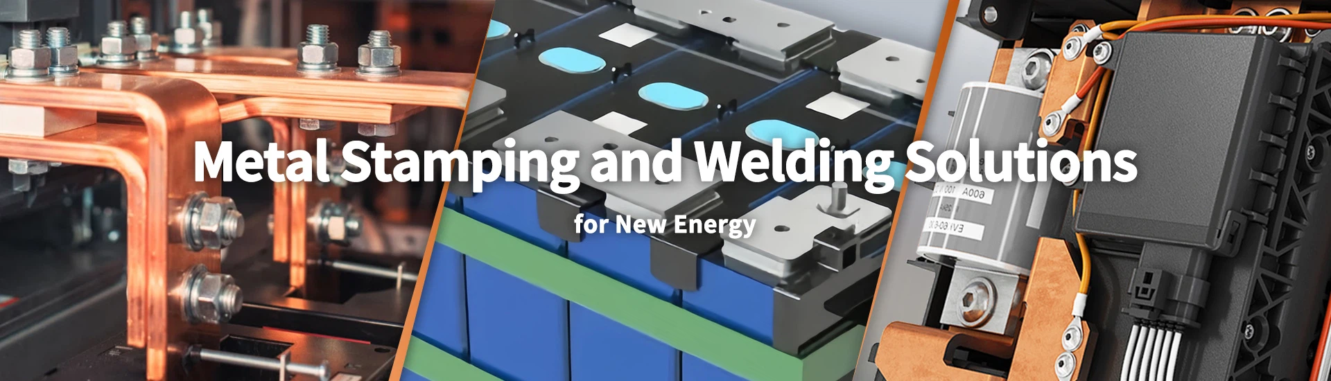
Custom Battery Cover Plate Manufacturer for EV and Energy Storage Batteries
Xiamen Apollo Stamping Welding Technology manufactures aluminum battery cover plates and integrated top-cover assemblies for prismatic lithium-ion batteries. The product range uses 3003-H14 aluminum, T2Y2 copper terminals, and engineered plastic insulation components. Manufacturing covers precision stamping, component forming, terminal assembly, and joining processes for EV power batteries and energy storage battery systems.
Apollo supports drawing-based DFM review, tooling development, and production inspection for custom battery cover plate projects. Engineering evaluation covers terminal positioning, sealing surfaces, explosion-proof valve interfaces, and insulation clearances. Critical dimensions and inspection criteria are established against approved drawings, with material traceability and PPAP Level 3 documentation available according to project requirements.
Request a Factory Direct Quote
Explore Our Battery Cover Plate Product Catalog
Compare aluminum battery lids, prismatic cell covers, and integrated safety assemblies for different battery enclosure configurations.
-
![Aluminum Battery Box Cover]() Add to Inquiry
-
![Aluminum Battery Boxes Cover]() Add to Inquiry
-
![Bettery Cover Plate]() Add to Inquiry
-
![Battery Aluminum Safety Cover Set]()
Battery Aluminum Safety Cover Set
Add to Inquiry -
![LFP Safety Cover Set]() Add to Inquiry
-
![Lithium-ion Battery Cover Plates]()
Lithium-ion Battery Cover Plates
Add to Inquiry -
![Power Battery Shell Cover Plate]()
Power Battery Shell Cover Plate
Add to Inquiry -
![Prismatic Lithium Battery Canopy]()
Prismatic Lithium Battery Canopy
Add to Inquiry -
![Aluminum Cover For Battery Cases]()
Aluminum Cover For Battery Cases
Add to Inquiry -
![Power Battery Cover Set]() Add to Inquiry
-
![Prismatic Lithium Battery Lid]() Add to Inquiry
-
![Aluminum Cover Plate For Battery]()
Aluminum Cover Plate For Battery
Add to Inquiry


Material Standards, Tooling & Forming Processes
A battery cover plate must maintain its specified geometry while accommodating sealing surfaces, terminal interfaces, and any integrated safety features. Material selection therefore depends on the battery design, required forming depth, corrosion environment, joining method and dimensional tolerances.
Aluminum alloys such as 3003 and 3005 may be considered for cover-plate applications where formability, mass and corrosion behavior are relevant. The final grade and temper must be confirmed against the customer's drawing and forming requirements. Alloy designation alone does not establish suitability for every battery chemistry, pressure condition, or welding process.
Precision Stamping and Forming
Battery cover plate manufacturing may include blanking, shallow drawing, embossing, hole punching, trimming, flange forming and local flattening. The process sequence depends on the geometry and the location of terminal openings, sealing edges and mounting features.
During tool development, the engineering review should consider:
Material flow: Punch radii, die clearance and blank-holder force must be matched to the alloy, temper and sheet thickness to limit cracking and wrinkling.
Springback compensation: Forming parameters and tool geometry should account for elastic recovery, particularly around sealing flanges and terminal mounting surfaces.
Flatness control: Local deformation during stamping or welding must not compromise the specified sealing interface.
Terminal location: Hole positions and mounting datums should be defined relative to the battery assembly's functional reference surfaces.
Tooling repeatability: First-article inspection and in-process checks should detect dimensional drift before it affects downstream assembly.
For covers incorporating safety vents, pressure-relief components, or electrical terminals, the design should distinguish the structural cover from the functional components installed in it. Vent opening characteristics and terminal insulation requirements must be specified and validated for the complete assembly.
Battery Cover Plate Specifications
| Parameter | Engineering specification | Verification method |
| Base material | Aluminum alloy such as 3003 or 3005, subject to design approval | Material certificate and grade verification |
| Sheet thickness | Defined by the approved drawing | Calibrated thickness gauge |
| Cover profile | Drawing-defined height, contour, and flange geometry | Optical measurement or CMM |
| Flatness | Customer-defined tolerance for the sealing interface | Surface measurement or specified fixture |
| Terminal openings | Position and diameter per drawing | Optical inspection or coordinate measurement |
| Formed edges | Burr, cracking, and wrinkling limits per inspection plan | Visual and dimensional inspection |
| Weld joint | Joint geometry and acceptance criteria defined by the assembly design | Visual inspection and qualified weld testing |
| Leak acceptance | Customer-specified limit and test conditions | Validated leak-test method |
| Insulation features | Material and electrical requirements according to the design | Dimensional and electrical testing as applicable |
The table defines the parameters that should be established during engineering review; it does not imply that every battery cover plate uses the same material, tolerance, or test limit.
For related battery enclosure requirements, see Aluminum Battery Case and Cover Components.
Advanced Joining, Insulation & Surface Treatments
The joining process for a battery cover plate depends on the cover material, housing material, joint geometry, and sealing requirement. Laser welding may be considered for aluminum cover-to-housing joints where controlled energy input and a suitable joint design can provide the required weld integrity.
Laser Welding and Sealing Interface Control
Before production approval, the welding procedure should define the joint configuration, fit-up gap, surface preparation, fixture method, and relevant process parameters. Excessive distortion, incomplete fusion, porosity, or inconsistent penetration may compromise joint performance and dimensional stability.
The engineering validation plan should address:
Joint fit-up: Confirm the permitted gap and alignment between the cover and housing.
Weld geometry: Define the weld path, effective joint dimensions, and acceptable surface condition.
Thermal deformation: Measure changes in cover flatness and terminal position after welding.
Joint integrity: Use an inspection or test method appropriate to the joint design and failure risks.
Leak verification: Where the assembly requires gas or liquid tightness, establish the test medium, pressure differential, stabilization time, and acceptance threshold.
Helium mass spectrometer leak detection may be suitable for assemblies with sufficiently stringent leak requirements and compatible test configurations. A leak-rate value such as \(1 \times 10^{-9}\ \mathrm{Pa \cdot m^3/s}\) should only be specified when required by the product design and validated by the actual test setup; it is not a universal acceptance limit for battery cover plates.
Terminal Insulation and Surface Protection
Where the cover plate integrates conductive terminals, the insulation system must maintain the required electrical separation between terminals and the metal cover. The specification should identify the insulating material, interface dimensions, creepage and clearance requirements where applicable, and the electrical tests required for the finished assembly.
Surface treatments should be selected according to the cover's environment and joining sequence. For example, a coating near a weld zone may require masking or removal before welding. Surface preparation, coating compatibility, and post-process corrosion protection should therefore be evaluated together rather than specified independently.
Relevant validation items may include:
Insulation resistance and dielectric withstand testing where required.
Terminal retention and dimensional verification.
Weld appearance and joint integrity assessment.
Leak testing under the defined acceptance conditions.
Environmental exposure testing based on the customer's qualification plan.
Request Custom Technical Evaluation
Quality Control & Certifications at Apollo
Battery cover plate inspection should be linked to the functions of the finished assembly. A cover may meet its external dimensions while still failing because of flange distortion, terminal misalignment, weld defects, or inadequate sealing. The inspection plan should therefore combine dimensional verification with joining and assembly-related tests.
Dimensional and Process Inspection
Optical measuring systems, calibrated gauges and CMM equipment can be selected according to the size, geometry and required measurement uncertainty of the component. Critical characteristics should be identified during drawing review and recorded in the inspection plan.
Recommended controls include:
Incoming verification of alloy grade, thickness and material condition.
First-article inspection of the formed profile, hole positions, and sealing surfaces.
In-process checks for forming cracks, wrinkles, burrs, and dimensional drift.
Post-weld inspection of cover flatness and terminal location.
Weld-joint evaluation using approved visual, destructive, or nondestructive methods as appropriate.
Leak testing using the specified equipment and validated procedure when the assembly requires a defined leak rate.
Quality Documentation and Traceability
For automotive programs, the customer-specific quality plan may require PPAP Level 3 documentation. Depending on the program and agreed submission scope, this may include the process flow diagram, PFMEA, control plan, material certificates, dimensional results, measurement-system studies, and process capability data.
IATF 16949:2016 and ISO 9001 should only be referenced as applicable company certifications after their current status and scope have been verified. Customer-specific approval requirements remain separate from general quality-system certification.
For repeat production, material batches, tooling revisions, and welding process records should be linked to finished-product lot identifiers. This allows dimensional or leak-test deviations to be investigated against the relevant production history.
Final Inspection and Packaging
Before shipment, the inspection plan should confirm part identification, required dimensions, specified surface condition, and the agreed test records. Packaging should protect thin aluminum flanges and machined or formed sealing surfaces from impact, deformation, contamination, and abrasion during transportation.
For assemblies with exposed terminals or insulating components, packaging instructions should also prevent contact damage and contamination that could affect downstream installation.
Frequently Asked Questions
Q: 1. Which aluminum alloy is suitable for a custom battery cover plate?
A: Aluminum alloys such as 3003 and 3005 may be considered depending on forming depth, corrosion exposure, thickness, and joining requirements. The final alloy and temper should be confirmed through drawing review and process validation. Suitability also depends on the cover's structural role and the requirements of the complete battery assembly.
Q: 2. How is the sealing performance of a welded battery cover plate verified?
A: The verification method depends on the specified leak limit, assembly design, and operating conditions. Helium mass spectrometer testing may be appropriate for stringent leak requirements, while other validated methods may suit different assemblies. Test pressure, stabilization time, fixture leakage, and acceptance criteria must be defined before inspection.
Q: 3. How can terminal position and cover flatness be controlled during mass production?
A: Critical dimensions should reference functional assembly datums and be checked after the forming and joining operations that can affect them. Tool compensation, stable fixtures, and first-article inspection help control variation. Post-weld measurements are important when thermal deformation may shift terminal locations or distort the sealing flange.
Q: 4. Can Apollo supply battery cover plates with integrated safety vents and insulated terminals?
A: The feasibility depends on the cover design, component sourcing, assembly method, and qualification requirements. Provide the drawing and identify whether the project requires only the stamped cover or a completed assembly. Safety-vent performance, terminal insulation, and sealing must be evaluated against the applicable product specifications.
Request a Custom Battery Cover Plate Quote
Send your 2D drawings in .DWG or PDF format, 3D models in STEP format, or a technical specification for your battery cover plate project.
To support an accurate engineering review, include the aluminum alloy and temper, sheet thickness, critical dimensions, sealing requirements, terminal configuration, joining method, annual demand, and any required leak-test limits.
Apollo can assess forming feasibility, tooling considerations, weld access, inspection requirements, and production risks before quotation. A preliminary DFM review and quotation within 24 hours can be requested for complete inquiries, subject to drawing complexity and engineering workload.
Submit your design to establish the applicable manufacturing route, quality documentation, and sample approval requirements before mass production.
We're well-known as one of the leading battery cover plate manufacturers and suppliers in China. Please feel free to buy high quality battery cover plate at competitive price from our factory. For more information, contact us now.
