

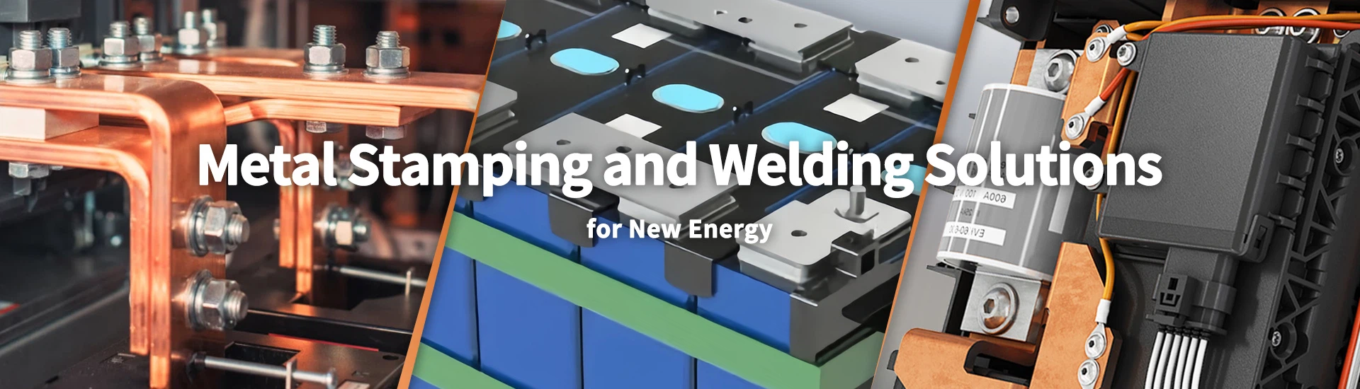
Custom Copper Welding Parts Manufacturer for EV and Electrical Applications
Xiamen Apollo Stamping Welding Technology manufactures copper welding parts for EV fuse components, electrical terminals, and high-current connection assemblies. Production covers T2 copper components, copper end caps, and welded contact structures, using resistance welding, tin brazing, and other drawing-specified joining processes. Material selection considers electrical conductivity, thermal properties, joint geometry and mechanical loading.
Apollo supports OEM manufacturing from drawing review to production. Engineering evaluation covers copper grade, component thickness, weld position, joint dimensions, and inspection requirements. Customers can define electrical resistance, mechanical strength, and dimensional acceptance criteria before production release. Material traceability and PPAP documentation can be arranged according to project requirements.
Request a Factory Direct Quote
Explore Our Copper Welding Parts Product Catalog
Review copper end caps, welded fuse contacts, and brazed copper assemblies for electrical and new-energy applications.
Material Standards, Tooling & Forming Processes
Copper welding parts are used where electrical conductivity, thermal transfer, and compact connection geometry are required. Material selection must consider more than copper purity alone. Grade, temper, thickness, surface condition, and joint design all affect forming behavior and welding performance.
For electrical components, C1100 or the specified T2 copper grade may be considered where high conductivity is required. The applicable material standard and conductivity acceptance value should be stated on the drawing or purchasing specification. Copper alloys such as brass may be used for mating or formed components when their mechanical properties and joining compatibility suit the design.
Copper's high thermal conductivity allows heat to dissipate rapidly from the joint. Welding process development therefore needs to account for material thickness, contact area, joint gap, surface oxides, and heat input. Excessive or insufficient heat input can lead to distortion, incomplete fusion, or inconsistent joint geometry, depending on the joining process.
Copper Welding Part Manufacturing Workflow
1. Drawing and material review: Confirm material grade, thickness, joint configuration, dimensional datums, and electrical requirements.
2. Material preparation: Remove oil, oxides, and other contaminants using a method compatible with the substrate and subsequent joining process.
3. Component forming: Stamp, cut, bend, or machine the parts to establish the required mating geometry.
4. Joint preparation and welding: Select a qualified joining process based on the copper grade, thickness, geometry, and production volume.
5. Post-weld inspection: Evaluate joint appearance, dimensions and required mechanical or electrical characteristics.
6. Final acceptance: Verify the finished assembly against the approved drawing, inspection plan, and packaging requirements.
Copper Welding Part Specifications
| Parameter | Specification basis | Inspection or verification |
| Copper material | C1100, T2 copper or customer-specified grade | Material certificate and grade verification |
| Copper alloy mating part | Brass or other specified conductive alloy | Material identification and drawing review |
| Material thickness | Defined by the approved component drawing | Calibrated thickness gauge |
| Joint geometry | Overlap, butt, lap, or other specified configuration | Dimensional inspection |
| Dimensional tolerance | Drawing-defined; ±0.01 mm only where validated for the feature and process | Optical measurement or CMM |
| Electrical conductivity | Specified material-grade acceptance value | Conductivity testing when required |
| Joint resistance | Customer-defined limit and measurement configuration | Four-wire resistance measurement where applicable |
| Mechanical strength | Specified tensile, shear, or pull-off requirement | Mechanical testing using an agreed fixture |
| Surface condition | As-welded, cleaned, plated, or otherwise specified | Visual inspection and applicable coating tests |
The table defines the information needed for technical review rather than fixed limits applicable to every copper welding part. Final values must be agreed upon for each component.
Tooling and Dimensional Control
Where copper welding parts include stamped or formed features, tooling design influences joint fit-up and downstream welding consistency. Hole position, flatness, bend angle, and mating-surface alignment should be controlled before welding to avoid forcing misaligned parts into position.
A tolerance of ±0.01 mm may be specified for suitable dimensions, but it should not be applied indiscriminately to all features. Feasibility depends on material thickness, part size, forming sequence, datum structure, and measurement uncertainty. Critical-to-quality dimensions should be identified during DFM review, with inspection methods established before mass production.
For related manufacturing capabilities, see Copper Metal Stamping Parts.
Advanced Joining, Insulation & Surface Treatments
Copper welding requires a joining process matched to the materials, section thickness, and electrical or mechanical function of the assembly. Resistance welding, laser welding, TIG welding, and brazing are different processes; they should not be treated as interchangeable or specified without considering the joint design.
Joining Process Selection
| Joining method | Typical engineering consideration | Required process verification |
| Resistance welding | Electrode force, current, weld time, contact condition, and heat distribution | Weld consistency, joint resistance, and mechanical strength as specified |
| Laser welding | Beam absorption, focus position, joint gap, penetration, and local heat input | Weld profile, penetration, and defect inspection |
| TIG welding | Heat input, filler selection where applicable, shielding gas, and distortion | Weld appearance, fusion quality, and dimensional stability |
| Brazing | Filler alloy, joint clearance, wetting, surface preparation, and thermal cycle | Joint coverage, void assessment where required, and mechanical testing |
Copper's reflectivity and thermal conductivity can make laser welding process development sensitive to surface condition, laser wavelength, power density, and joint geometry. A qualified process should establish a repeatable window for penetration and defect control. For dissimilar copper-to-aluminum joints, intermetallic compound formation must also be considered; such joints require a separate material-specific procedure and validation.
For copper-to-brass assemblies, the selected joining method must account for the alloy composition, zinc content, joint configuration, and thermal exposure. Excessive heating can cause distortion or metallurgical changes, while inadequate energy or poor surface preparation can produce incomplete bonding.
Joint Integrity and Electrical Performance
A sound copper welding part must meet the requirements of its intended function. For a current-carrying component, electrical resistance may be measured using a defined four-wire method with controlled contact locations and test conditions. For a load-bearing joint, tensile, shear, or pull-off testing may be required.
Acceptance criteria should distinguish between:
Surface appearance and visible weld defects.
Joint penetration or bonded-area requirements.
Electrical resistance under defined measurement conditions.
Mechanical strength under a specified loading direction.
Stability after thermal cycling or environmental exposure, when required by the application.
These checks should be linked to the customer's component specification. A single visual inspection cannot establish all of these performance characteristics.
Surface Treatment and Corrosion Control
Surface treatment is selected according to the electrical interface and operating environment. Tin, nickel, or silver plating may be specified for suitable copper components, while unplated copper may be acceptable where the design permits it. The coating specification should define thickness, coverage, substrate preparation, and inspection requirements.
For assemblies that undergo welding before plating, the process sequence must account for heat-affected areas and potential coating damage. If plating occurs before joining, the engineering review should consider coating behavior during the joining cycle and any resulting changes to joint quality.
For components exposed to humidity, vibration, or temperature cycling, the qualification plan may include contact resistance measurements before and after environmental conditioning. Coating thickness alone does not demonstrate long-term connection reliability.
Electrical insulation is not an inherent feature of a bare copper welding part. Where insulation is required, the assembly design must specify the insulation material, coverage, clearance, creepage distance, and dielectric withstand requirements separately.
Request Custom Technical Evaluation
Quality Control & Certifications at Apollo
Copper welding part inspection should cover the complete manufacturing sequence, from material identification and pre-weld dimensions to finished-joint evaluation. The inspection plan should identify critical dimensions, process checkpoints, test equipment, and acceptance criteria before production begins.
Inspection Plan for Copper Welding Parts
| Inspection stage | Control item | Verification method |
| Incoming material | Copper grade, thickness, and material condition | Material certificate and incoming inspection |
| Pre-weld preparation | Joint fit-up, surface contamination, and alignment | Visual and dimensional inspection |
| Welding process | Process parameters and repeatability | Approved welding procedure and process records |
| Welded joint | Surface defects, cracks, and incomplete joining | Visual inspection and additional NDT where specified |
| Electrical performance | Joint resistance where applicable | Calibrated resistance measurement system |
| Mechanical performance | Joint strength and failure mode | Tensile, shear or pull-off test as specified |
| Finished dimensions | Critical dimensions and deformation | Optical measurement, gauges or CMM where suitable |
| Batch release | Drawing compliance, traceability and packaging | Final inspection report and lot identification |
X-ray inspection or metallographic cross-section analysis may be appropriate for selected joint designs, but the method should be chosen according to the expected defect type, material thickness and acceptance standard. Neither method should be described as a universal requirement for every copper weld.
Quality-System and Documentation Support
Apollo identifies ISO 9001 and IATF 16949 among its quality-system credentials. The applicable certification scope and current validity should be confirmed for the purchasing program.
For automotive projects requiring PPAP Level 3, the submission package can be defined against the customer's requirements and the applicable PPAP edition. Depending on the project, documents may include:
Process Flow Diagram.
Process Failure Mode and Effects Analysis (PFMEA).
Control Plan.
Material test certificates.
Dimensional inspection results.
Measurement system analysis, where required.
Process capability data for designated critical characteristics.
Welding procedure and validation records, where applicable.
PPAP Level 3 should not be presented as automatically included with every order. The required submission level, sample quantity, test scope, and approval milestones should be agreed upon during quotation and project planning.
Production Consistency and Batch Traceability
For recurring orders, a defined control plan helps maintain consistency across material lots, tooling revisions and welding-process settings. Critical characteristics should have documented inspection frequency and reaction plans for out-of-specification results.
The finished parts should be packaged to prevent deformation, contamination, and damage to contact surfaces. Where traceability is required, batch labels should connect the shipped components to the applicable material and production records.
For broader joining capabilities, review Copper Welding Part Manufacturing.
Frequently Asked Questions About Copper Welding Parts
Q: 1. Which copper grade is suitable for electrical copper welding parts?
A: C1100 or T2 copper may be suitable when high electrical conductivity is required, but the final choice depends on the applicable material standard, temper, thickness, and joint design. The drawing should define the grade and acceptance criteria. Welding trials should confirm that the selected material and joining process meet the required performance.
Q: 2. How can weld defects be controlled when joining copper components?
A: Defect control starts with clean mating surfaces, consistent joint fit-up, and a process window matched to material thickness and geometry. Resistance welding requires control of current and electrode force; laser welding requires control of beam position and penetration. Inspection methods should target the expected defects and approved acceptance criteria.
Q: 3. How do you verify electrical resistance and mechanical strength in a copper welded joint?
A: Electrical resistance can be measured using a defined four-wire method with controlled contact locations and test conditions. Mechanical integrity may be evaluated through tensile, shear, or pull-off testing, depending on joint geometry. Acceptance limits should come from the component specification, not from a universal value applied to all copper assemblies.
Q: 4. Can Apollo manufacture custom copper welding parts from CAD drawings?
A: Apollo's copper welding category supports drawing-based component inquiries. Submit the 2D drawing, 3D model, material grade, joint configuration, annual volume, and required inspection criteria. Engineering review can then assess manufacturability, joining options, critical dimensions, and the inspection scope needed before a production quotation is finalized.
Request a Custom Copper Welding Part Quote
Copper welding assemblies must meet the specified electrical, mechanical, and dimensional requirements of their end application. Submit your drawings and technical requirements so Apollo can review the joint design, material selection, manufacturing route, and inspection plan before production approval.
Send your 2D drawings in .DWG or PDF format, 3D models in STEP format, or a technical specification listing copper grade, material thickness, joint geometry, surface treatment, and annual demand. Include electrical resistance limits, mechanical test requirements, and environmental conditions where applicable.
Apollo can evaluate the submitted information for DFM considerations, joining-process selection, and quality documentation requirements. A preliminary DFM review and quotation within 24 hours can be targeted for complete inquiries, subject to drawing complexity and engineering review requirements.
We're well-known as one of the leading copper welding part manufacturers and suppliers in China. Please feel free to buy high quality copper welding part at competitive price from our factory. For more information, contact us now.
