

Aluminum Welding Parts Manufacturer for Custom Aluminum Welded Components
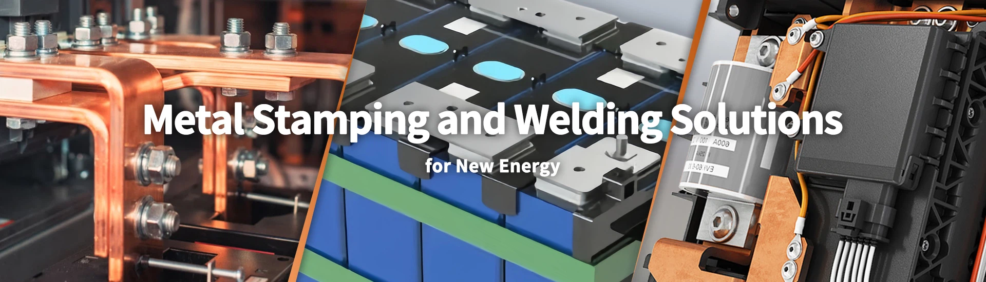
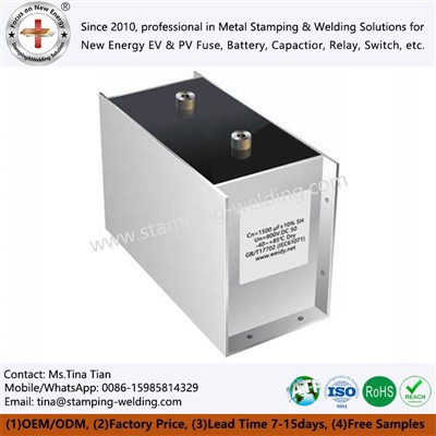
Xiamen Apollo Stamping Welding Technology manufactures aluminum welding parts for capacitor housings, automotive components, power equipment, and industrial assemblies. Production materials include 3003, 5052, and 6061 aluminum alloys, selected according to strength, formability, corrosion exposure, and joint requirements. Manufacturing processes include precision cutting, forming, laser welding, TIG welding, and MIG welding.
Apollo supports OEM production from drawing review to finished welded assemblies. Engineering evaluation covers joint geometry, material thickness, fixture positioning, weld penetration, and post-weld dimensional requirements. For repeat production, inspection plans can define critical dimensions, weld acceptance criteria, material traceability, and customer-specific PPAP Level 3 documentation.
Request a Factory Direct Quote
Explore Our Aluminum Welding Parts Product Catalog
Review our aluminum welded housings and components to identify suitable structures, joining methods, and drawing-based manufacturing options.
-
![GE Protective Capacitors Aluminium Can]()
GE Protective Capacitors Aluminium Can
Add to Inquiry -
![Capacitor Aluninum Case]() Add to Inquiry
-
![Capacitor Aluminum Square Case]()
Capacitor Aluminum Square Case
Add to Inquiry -
![Cylindrical Aluminium Can Energy Storage Pulse Filter Capacitor]()
-
![Aluminium Can For Metalized Film DC Filter Capacitors]()
Aluminium Can For Metalized Film DC Filter Capacitors
Add to Inquiry -
![Aluminum Can For Power Factor Correction Capacitor]()
Aluminum Can For Power Factor Correction Capacitor
Add to Inquiry -
![Film Power Capacitor Aluminium Can]()
Film Power Capacitor Aluminium Can
Add to Inquiry -
![Cylindrical Capacitors Aluminum Shell]()
Cylindrical Capacitors Aluminum Shell
Add to Inquiry -
![Tin Plated Can For Low Voltage Shunt Capacitor]()
Tin Plated Can For Low Voltage Shunt Capacitor
Add to Inquiry -
![Power Converter Capacitor Can]() Add to Inquiry
-
![Aluminium Capacitor Cans]() Add to Inquiry
-
![Storage Capacitor Aluminium Cans]()
Storage Capacitor Aluminium Cans
Add to Inquiry




Material Standards, Tooling & Forming Processes
Aluminum welding parts require material and process selection based on the alloy series, temper, section thickness, and service environment. The alloy designation alone does not establish weldability or final joint strength. The engineering review should also consider the forming history, surface condition, restraint during welding, and any post-weld machining or finishing operations.
Aluminum Alloy Selection
5052 aluminum alloy is used in sheet-metal applications requiring corrosion resistance and formability. It may be suitable for fabricated covers, brackets, and enclosure components, subject to the required strength and joining configuration.
6061 aluminum alloy is commonly used for structural parts and machined components where strength and machinability are relevant. Its heat-treated condition must be considered because welding can reduce strength in the heat-affected zone. If the design relies on specified temper-dependent properties, the joint region requires appropriate engineering evaluation.
3003 aluminum alloy is used in applications requiring formability and corrosion resistance. Its suitability depends on the component geometry, load, and welding procedure.
Final material selection should follow the customer drawing and applicable material standard. Substituting one alloy or temper for another without approval may change forming behavior, corrosion performance, and weld qualification requirements.
Tooling, Part Preparation and Weld-Fixture Design
For stamped and welded components, dimensional control begins before welding. Blanking and forming determine the initial edge quality, mating clearance and contact between joint surfaces. Burrs, oxide layers, oil, and other contamination can affect weld consistency.
Fixtures should locate the part from defined datums and control movement during thermal input. Thin aluminum components may require balanced clamping, a qualified weld sequence and controlled heat input to reduce distortion. Where holes, mounting faces or sealing surfaces have tight tolerances, inspection should be planned both before and after welding.
Recommended engineering checks include:
Verify the alloy, temper, and thickness against the drawing.
Define joint type, weld access, edge preparation, and allowable gap.
Establish fixture datums and dimensional inspection points.
Evaluate heat-affected zones where structural properties are critical.
Define post-weld machining, surface treatment, and assembly interfaces.
Aluminum Welding Parts Specifications Table
| Parameter | Engineering requirement | Verification method |
| Aluminum alloy | 3003, 5052, 6061 or customer-specified grade | Material certificate and grade verification |
| Temper | As specified on the approved drawing | Material documentation |
| Material thickness | Drawing-defined range | Calibrated thickness gauge |
| Joint design | Butt, lap, fillet, or other drawing-defined configuration | Drawing and weld-procedure review |
| Weld penetration | Defined by joint design and service requirements | Section examination or qualified NDT method |
| Dimensional tolerance | Drawing-specific; ±0.01 mm only where validated and applicable | CMM, optical measurement, or calibrated gauges |
| Weld strength | Acceptance limit based on design loads and test method | Tensile, shear, or other specified mechanical test |
| Surface condition | Defined limits for oxidation, spatter, and visible defects | Visual inspection and agreed acceptance criteria |
| Corrosion protection | Specified coating or finishing system | Coating inspection and applicable test |
| Production traceability | Lot and process records according to project requirements | Inspection records and batch identification |
These entries define the information to be agreed upon during project engineering; they are not blanket performance guarantees for every aluminum welded component.
For other metal joining requirements, review Custom Metal Welding Parts.
Advanced Joining, Insulation & Surface Treatments
Aluminum joining processes should be selected according to the alloy, thickness, joint access, production volume and required mechanical performance. A process suitable for a thin cover may not be suitable for a thick structural bracket or a high-current electrical connector.
Aluminum Laser Welding
Laser welding concentrates energy within a defined weld zone and can be suitable for components requiring localized heat input and repeatable joint positioning. Successful production depends on joint fit-up, beam alignment, surface preparation, shielding conditions and parameter control.
The process qualification should establish acceptable penetration, fusion continuity, porosity limits and dimensional distortion. Cross-sectional examination can be used where required to verify penetration and joint geometry. The final acceptance criteria should reflect the part's mechanical or electrical function rather than visual appearance alone.
TIG and MIG Welding
TIG welding provides controlled heat input for suitable aluminum joints and may be used for prototypes, repairable fixtures or lower-volume assemblies. MIG welding can support higher deposition rates and production throughput where joint geometry and component thickness permit.
Both processes require suitable filler selection, shielding gas, surface preparation, and a qualified welding procedure. The welding plan should address the alloy combination, expected distortion, access to the joint, and the inspection method.
Copper-to-Aluminum Joining
Where a design requires copper-to-aluminum joining, the material interface must be evaluated separately from aluminum-to-aluminum welding. Differences in melting behavior and the formation of brittle intermetallic compounds can reduce joint ductility and fatigue resistance.
Depending on the geometry and electrical requirements, possible routes may include a qualified laser process, resistance joining, or a mechanically assisted transition design. The chosen process must be validated for interface integrity, mechanical loading, and electrical performance. No single welding method can be assumed suitable for all Cu-Al combinations.
Surface Treatment and Insulation
Surface treatment is selected according to the part's operating environment and interface requirements. Options may include conversion coatings, anodizing, specified paint systems, or other compatible finishes. Not every coating is appropriate for every welded alloy or electrical contact surface.
For electrical assemblies, insulation materials should be selected against the specified working voltage, dielectric withstand requirement, operating temperature, and creepage or clearance design. A coating's nominal dielectric strength does not independently establish the withstand voltage of the complete assembly.
Joining Process Comparison
| Process | Potential application | Main controls |
| Laser welding | Localized joints and suitable precision assemblies | Fit-up, beam alignment, penetration and porosity |
| TIG welding | Selected thin or medium-section aluminum components | Heat input, shielding, filler, and distortion |
| MIG welding | Suitable for production welds requiring higher deposition rates | Wire feed, arc parameters, shielding and weld profile |
| Resistance welding | Suitable for overlapping joints and compatible material combinations | Electrode force, current, weld time and contact condition |
| Mechanical joining | Assemblies where fusion welding is unsuitable | Fastener specification, clamp load and interface integrity |
The final process should be selected only after reviewing the actual component design and acceptance requirements.
Request Custom Technical Evaluation
Quality Control & Certifications at Apollo
Quality assurance for aluminum welding parts should cover incoming materials, formed-part geometry, weld integrity, finished dimensions, and batch traceability. Inspection requirements should be defined by drawing revision and component risk, with clear acceptance criteria for critical-to-quality characteristics.
Incoming Material and Dimensional Inspection
Incoming checks should verify the alloy designation, temper, thickness and material documentation. During production, formed dimensions and joint preparation should be monitored to prevent fit-up variation from becoming a weld defect.
CMM equipment, optical measurement systems and calibrated gauges can be selected according to the component's size, geometry and tolerance requirements. Measurement-system capability must be suitable for the tolerance being inspected; the accuracy of a particular instrument should not be treated as the tolerance of the finished part.
Weld Integrity and Non-Destructive Testing
Visual inspection can identify surface discontinuities and visible profile defects, but it cannot establish internal weld integrity by itself. Depending on joint geometry and defect criteria, inspection may include:
Cross-sectional examination for penetration and fusion assessment.
Dye penetrant testing for suitable surface-breaking defects.
Radiographic testing where the material thickness, geometry, and defect type make the method appropriate.
Mechanical testing on production-representative samples.
Dimensional inspection before and after welding.
Electrical resistance or temperature-rise testing for components carrying current, when specified.
The selected inspection method should be capable of detecting the defect types relevant to the component. Radiographic inspection, for example, is not equally effective for every crack orientation or joint configuration.
Quality Systems and Production Documentation
Apollo's applicable quality certifications and manufacturing scope should be verified against current certificates before publication. Where IATF 16949:2016 or ISO 9001 is claimed, the certificate's validity, site, and scope should match the actual manufacturing activity.
For automotive projects, PPAP Level 3 may be required by the customer. Depending on the agreed submission scope, the package can include process flow, PFMEA, control plan, dimensional results, material certifications, process capability data and other customer-specific records.
Process capability indices such as Cpk should be reported only where the data collection method, sample size, process stability, and acceptance criteria support the result. They should not be inferred from a small number of prototype parts.
Production Consistency and Delivery
For repeat production, inspection plans should identify the critical dimensions, welding parameters and sampling frequency. Where appropriate, the manufacturing record should link the material lot, tooling revision, welding procedure and finished-part batch.
Packaging should protect the weld area and finished surfaces from impact, contamination and corrosion during transport. For parts with machined interfaces or tight assembly tolerances, packaging design should also prevent deformation during storage and handling.
Frequently Asked Questions
Q: 1. Which aluminum alloys can be used for custom welding parts?
A: Commonly considered alloys include 3003, 5052, and 6061, but suitability depends on the component's load, forming history, thickness, and welding process. Temper is also important because welding can reduce strength in heat-treated alloys. Final selection should follow the approved drawing and qualified joining procedure.
Q: 2. How can porosity and incomplete fusion be controlled in aluminum welding?
A: Control starts with clean joint surfaces, suitable oxide removal, correct shielding, stable fit-up, and qualified welding parameters. Inspection may include visual examination, cross-sectional analysis, or an appropriate non-destructive method. Acceptance limits should be specified according to the joint's function and relevant product requirements.
Q: 3. Can aluminum welding parts meet a ±0.01 mm dimensional tolerance?
A: A ±0.01 mm tolerance may be achievable for selected machined or closely controlled features, but it should not be assumed for every welded dimension. Thermal distortion, part size, thickness, and fixture design affect the result. Critical dimensions require a documented capability assessment and suitable measurement method.
Q: 4. How should copper-to-aluminum welded components be qualified?
A: Cu-Al joints require evaluation of interface formation, brittle intermetallic compounds, mechanical strength, and electrical resistance where applicable. Qualification should use representative materials and joint geometry, followed by appropriate mechanical and environmental tests. The acceptance criteria should reflect the actual operating current, load, and thermal cycling conditions.
Request an Aluminum Welding Parts Engineering Review
Submit your 2D drawings in .DWG or PDF format, 3D models in STEP format, or a component specification listing the aluminum alloy, temper, thickness, joint geometry, dimensional tolerances, and surface treatment requirements.
Apollo can review the proposed manufacturing route, fixture requirements, weld inspection plan, and critical dimensions before quotation. For electrical components, include current-carrying requirements, resistance limits, and applicable thermal or environmental test conditions.
A preliminary DFM review and quotation can be scheduled after the required information is received. If a 24-hour response is needed, identify the project deadline in your inquiry so the team can confirm availability.
We're well-known as one of the leading aluminum welding part manufacturers and suppliers in China. Please feel free to buy high quality aluminum welding part at competitive price from our factory. For more information, contact us now.
