

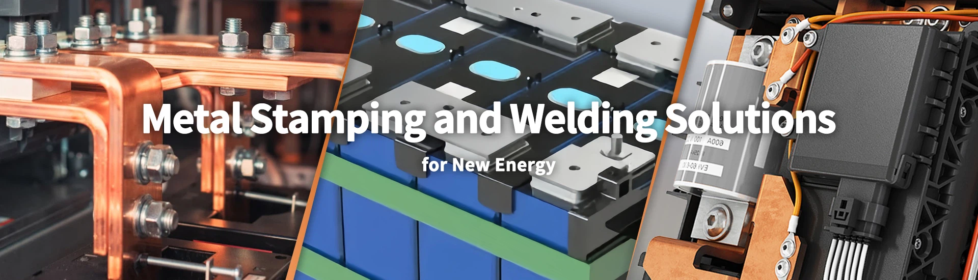
Custom Fuse Cap and Contact Manufacturer for EV, PV, and NH Fuse Assemblies
Xiamen Apollo Stamping Welding Technology manufactures custom Fuse Cap And Contact assemblies for EV, PV, and NH fuse links. Components are produced using T2Y2 high-conductivity copper and H65 brass, with material specifications selected according to electrical requirements and forming conditions. Production covers precision stamping, drawing, riveting, resistance welding, silver brazing and surface plating.
As a direct manufacturer with in-house stamping tooling and joining capabilities, Apollo supports drawing review, DFM assessment, and OEM production. Critical dimensions, contact geometry, plating thickness and joint strength are defined against customer drawings. Material certificates, dimensional inspection reports, and PPAP Level 3 documentation can be arranged according to project requirements.
Request a Factory Direct Quote
Explore Our Fuse Cap and Contact Product Catalog
Browse copper cap assemblies, welded terminals and brass contact components for EV, PV and industrial fuse applications.
-
![Fuse Cap And Contact Tin Welding]()
Fuse Cap And Contact Tin Welding
Add to Inquiry -
![Copper Cap And Fuse Terminal]() Add to Inquiry
-
![Fuse End Cap And Contact]() Add to Inquiry
-
![Outer End Cap And Terminal Welded Assembly Set]()
Outer End Cap And Terminal Welded Assembly Set
Add to Inquiry -
![Cap And Contact For Battery Power And Auxiliary Fuses]()
Cap And Contact For Battery Power And Auxiliary Fuses
Add to Inquiry -
![Copper Cap And Fuse End Tag]() Add to Inquiry
-
![Copper Cap And Contact For Electric Vehicle Fuse]()
Copper Cap And Contact For Electric Vehicle Fuse
Add to Inquiry -
![Copper Cap Contact For High Voltage EV Fuse]()
Copper Cap Contact For High Voltage EV Fuse
Add to Inquiry -
![Forged Copper Components]() Add to Inquiry
-
![Copper Cap Contact For Electric Vehicles]()
Copper Cap Contact For Electric Vehicles
Add to Inquiry -
![Copper External Cap]() Add to Inquiry
-
![Copper Cap And Fuse Contact]() Add to Inquiry


Material Standards, Tooling & Forming Processes
Fuse cap and contact manufacturing begins with the selection of conductive materials that meet electrical, mechanical, and forming requirements. Copper is commonly specified for conductive end caps and contact components, while brass may be selected for inner caps requiring a different balance of stiffness, formability and dimensional retention.
Material grade, temper and thickness influence drawing force, wall thinning, springback and edge quality. These factors should be evaluated against the finished geometry rather than treated as independent material properties. For deep-drawn caps, punch radius, die clearance, blank-holder force and lubrication affect the risk of wrinkling, tearing and uneven wall thickness.
Progressive die stamping can produce repeatable contact profiles and terminal features at production volumes suited to the tooling design. Drawing operations form cylindrical or shaped caps, while secondary machining, riveting or joining processes complete the component assembly. The tooling plan should define datum references, critical dimensions, burr direction, and inspection points before mass production.
For custom projects, provide the 2D drawing or 3D CAD model with material grade, thickness, annual volume, and assembly requirements. This information allows manufacturing engineering to review forming feasibility, tooling complexity, and the dimensional controls required for production release.
Fuse Cap and Contact Technical Specifications
| Parameter | Specification basis | Inspection method |
| Conductive material | Copper or specified copper alloy | Material certificate and grade verification |
| Inner cap material | Brass or specified alternative | Incoming material inspection |
| Material thickness | Defined by approved drawing | Calibrated thickness gauge |
| Critical dimensions | Customer drawing and agreed tolerances | Optical measurement or CMM |
| Formed profile | Diameter, height, flatness, and wall geometry as applicable | Dimensional inspection |
| Edge condition | Burr direction and maximum permitted burr height | Visual and dimensional checks |
| Contact geometry | Mating dimensions and contact area per design | Optical measurement and functional gauging |
| Production process | Progressive stamping, drawing, and secondary forming as applicable | First-article and in-process inspection |
The applicable limits must be established for each component drawing. A tolerance of ±0.01 mm should only be specified where the part geometry, tooling capability, and inspection method have been validated.
Tooling Controls for Repeatable Production
Forming geometry: Confirm punch and die radii against the required cap depth and material thickness.
Material flow: Review areas susceptible to tearing, wrinkling, or local thinning.
Burr control: Specify the permitted burr height and its orientation relative to the assembly interface.
Tool wear: Monitor critical die features to detect dimensional drift across production lots.
First-article approval: Verify the finished part against the approved drawing before volume production.
For copper cap and contact configurations, review the Copper Cap and Fuse Contact product page.
Advanced Joining, Insulation & Surface Treatments
The connection between a fuse cap and its contact terminal must meet the electrical and mechanical requirements defined for the finished fuse. Apollo's published product range includes resistance-welded, soldered and brazed cap-and-contact assemblies. Process selection should account for substrate materials, joint geometry, required production rate, and the thermal exposure permitted by the design.
Resistance welding relies on controlled current, electrode force, weld time, and electrode condition. Variations in these parameters can affect joint consistency and mechanical retention. For soldering and silver brazing, surface cleanliness, joint clearance, filler material, and heating profile influence wetting and joint formation. The appropriate process should be established through sample evaluation and a defined inspection plan.
Surface Plating and Contact Interface Requirements
Tin, nickel and silver plating are selected according to the component's electrical interface, corrosion exposure and operating conditions. The specification should identify the coating system, substrate, minimum local thickness, measurement location, and acceptance method.
A plating thickness of 3–10 µm may be considered for evaluation where appropriate to the coating system and component design, but it is not a universal requirement for every fuse cap or contact. The final thickness must follow the approved drawing and functional qualification criteria.
For applications subject to vibration, thermal cycling, or repeated contact movement, the qualification plan should consider the stability of the contact interface. Coating thickness alone does not establish resistance to fretting corrosion or prove long-term electrical performance.
Recommended process checks include:
Plating thickness measurement at specified locations.
Surface inspection for bare areas, blistering, or visible coating defects.
Joint resistance measurement using an agreed test method.
Pull-off or tensile testing against a defined acceptance limit.
Environmental testing based on the actual operating temperature and exposure conditions.
Joining Process Selection
| Assembly type | Candidate process | Primary control |
| Copper end cap and terminal | Resistance welding | Joint resistance and mechanical retention |
| Copper cap and contact assembly | Soldering or brazing | Wetting, joint formation, and thermal exposure |
| Formed brass inner cap | Stamping and drawing | Cracking, dimensional stability and fit |
| Plated contact component | Tin, nickel or silver plating as specified | Coating thickness and surface condition |
| Mixed-material joint | Qualified joining method | Material compatibility and joint integrity |
Quality Control & Certifications at Apollo
Quality control for fuse caps and contacts should cover incoming materials, formed dimensions, surface treatment, joining integrity, and finished-part acceptance. The inspection plan should identify critical-to-quality characteristics and define how each characteristic is measured, recorded, and released.
Dimensional checks may use optical measurement systems, calibrated gauges or CMM equipment where appropriate to the component geometry. Plated components require a coating inspection method suitable for the specified coating and substrate. Welded and brazed assemblies may require visual examination, electrical resistance measurement, mechanical testing, or destructive section analysis according to the customer's requirements.
For automotive programs, Apollo can discuss the required PPAP documentation and submission scope with the customer. Depending on the project, this may include a process flow diagram, PFMEA, control plan, material certificates, dimensional results, and process capability data. IATF 16949 and ISO 9001 requirements should be applied within the verified scope of the relevant quality systems.
A component inspection report should distinguish measured results from general process descriptions. Where a customer requires Cpk or other process capability evidence, the sampling plan, measurement system, and acceptance criteria should be agreed before the study begins.
Recommended Quality Inspection Plan
| Inspection stage | Control item | Quality record |
| Incoming materials | Grade, thickness and material condition | Material certificate and incoming inspection record |
| First article | Critical dimensions and formed profile | First-article dimensional report |
| Stamping and drawing | Burrs, cracks, wrinkles and dimensional drift | In-process inspection record |
| Joining | Joint appearance, resistance and mechanical retention where specified | Weld inspection and test results |
| Plating | Coating type, thickness and surface condition | Plating certificate or measurement report |
| Final inspection | Drawing compliance, quantity and identification | Final inspection and lot traceability records |
| Automotive program | Required PPAP submission and process capability evidence | Customer-approved submission package |
Batch Traceability and Production Release
For repeat orders, the control plan should link material lots, tooling revisions, surface-treatment batches and joining-process records to the finished product lot. This structure supports investigations when a dimensional deviation, coating defect or electrical connection issue is identified.
Packaging should protect formed caps from deformation and prevent scratches or contamination on contact surfaces. The packing method, labeling, and batch identification should follow the customer's storage, handling, and traceability requirements.
Frequently Asked Questions About Fuse Cap and Contact
Q: 1. Which materials are suitable for custom fuse caps and contacts?
A: Copper is commonly used for conductive end caps and contact components. Brass may be selected for inner caps or formed parts with different mechanical and forming requirements. The final grade depends on electrical loading, component geometry, joining method, environmental exposure, and the approved material specification.
Q: 2. How is dimensional consistency maintained in deep-drawn fuse caps?
A: Dimensional consistency depends on material thickness, temper, punch and die geometry, forming force, and tool condition. First-article inspection should verify critical dimensions and wall geometry. During volume production, defined inspection intervals help identify tool wear and dimensional drift before nonconforming parts accumulate.
Q: 3. How can the reliability of a welded fuse contact be verified?
A: Verification may include visual inspection, electrical resistance measurement, and pull-off or tensile testing against defined limits. The appropriate method depends on the joint design and operating conditions. For qualification, the test setup, sample quantity, acceptance criteria, and any thermal-cycle requirements should be agreed in advance.
Q: 4. What information is required for an OEM fuse cap and contact quotation?
A: Provide the 2D drawing or 3D CAD file, material grade, thickness, surface finish, joining requirements, and estimated annual volume. Include critical tolerances, contact resistance limits, and mechanical test requirements where applicable. These inputs allow engineering to assess tooling, manufacturing feasibility, inspection scope, and quotation assumptions.
Request a Custom Fuse Cap and Contact Quote
Fuse cap and contact performance depends on material selection, formed geometry, surface condition, and joining quality. Submit your drawings and technical requirements so Apollo can review manufacturability, tooling needs, and inspection criteria before production release.
Send 2D drawings in .DWG or PDF format, 3D CAD files in STEP format, or a specification sheet containing material grade, dimensions, plating, joining requirements, and annual demand. Include contact resistance, pull-off force, and environmental test requirements where applicable.
Apollo can review the supplied information for DFM considerations, process selection, and quotation scope. A preliminary review within 24 hours can be targeted for complete inquiries, subject to drawing complexity and specification completeness.
We're well-known as one of the leading fuse cap and contact manufacturers and suppliers in China. Please feel free to buy high quality fuse cap and contact at competitive price from our factory. For more information, contact us now.
Electrical Fuse Components, Fuse Link Contact And End Cap For Auto Car, Inner Cap