

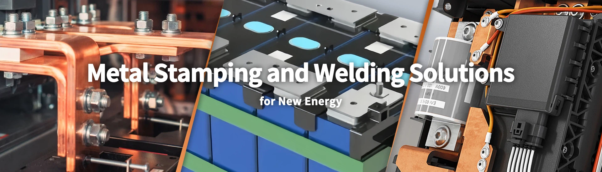
Direct-Factory Busbar Manufacturer for Copper, Laminated, and Flexible Busbar Solutions
Xiamen Apollo Stamping Welding Technology manufactures customized busbars for EV battery systems, energy storage equipment, power electronics, and industrial electrical applications. Our production integrates precision stamping, CNC machining, welding, and insulation processes using high-conductivity copper materials such as C1100 and T2 copper with conductivity up to 100% IACS.
Our engineering team supports drawing review, DFM optimization, and mass production with controlled dimensions, surface treatment options, and complete quality documents. From prototype development to high-volume supply, Apollo provides OEM busbar manufacturing based on customer electrical parameters, mechanical requirements, and PPAP Level 3 documentation.
Request a Factory Direct Quote
Explore Our Busbar Product Catalog
Select suitable copper, laminated, flexible, and insulated busbar solutions designed for high-current electrical connection systems.
-
![Stamping Aluminum Parts]() Add to Inquiry
-
![Aluminum Wall Brackets]() Add to Inquiry
-
![Custom Aluminum Stamping]() Add to Inquiry
-
![Aluminum Metal Stamping]() Add to Inquiry
-
![Aluminum Mounting Bracket Tube Clamp For Bullbar Roof Rack Roll Cage]()
-
![Aluminum Wall Bracket]() Add to Inquiry
-
![Aluminum Stamp]() Add to Inquiry
-
![Aluminum Metal Stamping Parts]() Add to Inquiry
-
![Metal Stamping Of Aluminum Parts]()
Metal Stamping Of Aluminum Parts
Add to Inquiry -
![Aluminum Alloy Solar Panel Mounting Bracket]()
Aluminum Alloy Solar Panel Mounting Bracket
Add to Inquiry -
![Premium Polished Aluminum Sign Mount Bracket]()
Premium Polished Aluminum Sign Mount Bracket
Add to Inquiry -
![Aluminum Clamp Hook For Roof Photovoltaic Support]()
Aluminum Clamp Hook For Roof Photovoltaic Support
Add to Inquiry


Material Standards, Tooling & Forming Processes
Aluminum stamping part performance depends on alloy composition, temper, sheet thickness, and forming geometry. The material must satisfy the component's structural load, corrosion exposure, dimensional stability, and surface finish requirements without exceeding the forming limits of the selected process.
Commonly specified alloys include 5052 for applications requiring good corrosion resistance and formability, 6061 where strength and subsequent machining are relevant, and 3003 for suitable general-purpose formed components. These grades are not interchangeable. The final choice must account for the required temper, forming severity, mechanical properties, and downstream processing.
Alloy Selection for Aluminum Stamping Parts
5052 aluminum alloy: Often considered for formed brackets, covers, and enclosures requiring corrosion resistance and good formability. Bend radius and temper affect cracking risk.
6061 aluminum alloy: May be appropriate for components requiring higher strength or machining after forming. Its formability depends on temper, thickness, and the severity of the forming operation.
3003 aluminum alloy: Commonly considered for applications requiring good formability and corrosion resistance, subject to the specified load and dimensional requirements.
Other specified grades: Can be assessed against the drawing, material availability, and manufacturing process.
For deep-drawn parts, blank geometry, punch radius, die clearance, lubrication and blank-holder force must be coordinated. Excessive tensile strain can cause localized thinning or fracture, while insufficient restraint can lead to wrinkling. For bent parts, springback compensation should be developed using material data and trial-forming results rather than a fixed correction factor.
Progressive die stamping is suitable for parts requiring repeated punching, notching, and forming operations in a controlled sequence. Compound or single-operation tooling may be more appropriate for simpler geometries or lower production volumes. Tool selection should account for part geometry, dimensional requirements, annual demand, and expected tool maintenance.
Aluminum Stamping Parts Specifications Table
| Parameter | Engineering consideration | Verification method |
| Aluminum alloy | 3003, 5052, 6061 or drawing-specified grade | Material certificate and grade verification |
| Material temper | Selected according to forming and mechanical requirements | Material documentation |
| Sheet thickness | Defined by drawing and applicable material tolerance | Calibrated thickness gauge |
| Hole position | Controlled from drawing datums | Optical measurement or CMM |
| Bend angle | Verified after springback and final forming | Angle gauge or dimensional inspection |
| Critical dimensions | Drawing-defined tolerance; ±0.01 mm only where validated | CMM, optical measurement, or dedicated gauge |
| Edge quality | Burr height and edge condition defined by the drawing | Visual inspection and burr measurement |
| Surface finish | As-formed, anodized, painted, or otherwise specified | Visual inspection and coating tests |
| Mechanical performance | Strength and load requirements determined by application | Material testing or component load test as specified |
These values describe the inspection framework, not universal production limits. Actual alloy, temper, dimensional tolerance and acceptance criteria must be confirmed for each part number.
Tooling Design and Dimensional Stability
A stable aluminum stamping process begins with a clear drawing datum structure and an identified set of critical-to-quality dimensions.
Die clearance: Set according to alloy, thickness, edge-quality requirements, and tooling configuration.
Forming radii: Select to reduce localized strain and cracking while meeting the required geometry.
Springback control: Verify bend angles and formed profiles during tool trials; compensate where the design permits.
Burr control: Specify the permitted burr height and orientation where parts interface with mating components or seals.
Tool wear: Monitor punches, cutting edges, and forming surfaces to limit dimensional drift during production.
Sample approval: Confirm critical dimensions and visual acceptance before authorizing mass production.
For projects requiring a dedicated tool, Apollo can review the proposed geometry, material specification, and production quantity before tooling development. See Custom Aluminum Stamping for related manufacturing capabilities.
Advanced Joining, Surface Treatments & Corrosion Protection
Aluminum stamping parts may require secondary machining, riveting, welding, anodizing, or coating after forming. Process selection should reflect the alloy, temper, component geometry, service environment, and assembly method.
Joining Options for Aluminum Stamped Components
Mechanical fastening and riveting are suitable for assemblies where the joint design allows the required load transfer and access for installation. Welding may be considered when a permanent joint is needed, but aluminum's oxide layer, thermal conductivity and alloy-specific response require suitable surface preparation and process parameters.
Where laser welding is specified, the joint geometry, material compatibility, fit-up, heat input and penetration requirements should be established during process qualification. For aluminum-to-steel or aluminum-to-copper assemblies, the joining procedure must address material compatibility and the potential formation of brittle intermetallic phases. The suitability of a process must be verified for the actual joint rather than inferred from the base material alone.
Surface Treatment Selection
| Surface treatment | Typical purpose | Engineering considerations |
| Anodizing | Surface protection and appearance | Alloy response, coating thickness, dimensional change, and contact areas |
| Powder coating | Protective and decorative coating | Edge coverage, pretreatment, film thickness and curing conditions |
| Wet painting | Specified color and protective finish | Adhesion, environmental exposure and coating thickness |
| Chemical conversion treatment | Surface preparation or corrosion protection | Substrate compatibility and subsequent coating requirements |
| As-formed finish | Avoid unnecessary finishing operations | Surface marks, handling scratches, and cosmetic acceptance |
For outdoor photovoltaic mounting components, salt spray testing should follow the project specification and applicable test method. A test duration such as 1,000 hours must not be treated as a universal requirement or a direct prediction of field service life; acceptance depends on the coating system, test conditions, and the customer's qualification criteria.
Dimensional Control After Finishing
Coating thickness and surface-treatment processes may affect hole sizes, mating clearances, contact surfaces, and assembly fit. For components with tight tolerances, the drawing should specify whether dimensions apply before or after finishing.
Inspection planning should identify:
Critical hole diameters and mounting pitch.
Coating thickness and coverage requirements.
Masked surfaces or electrical contact areas, where applicable.
Corrosion test method and acceptance criteria.
Cosmetic standards for scratches, dents, and visible forming marks.
For photovoltaic mounting applications, see Aluminum Metal Stamping Parts for related aluminum components.
Request Custom Technical Evaluation
Quality Control & Certifications at Apollo
Quality control for aluminum stamping parts should link incoming material verification, tooling approval, in-process measurement, and final inspection. The control plan should identify critical dimensions, measurement methods, inspection frequency, and the response required when a result falls outside the approved tolerance.
Recommended Inspection Stages
| Stage | Control item | Inspection evidence |
| Incoming material | Alloy grade, temper and thickness | Material certificate and incoming inspection record |
| Tool development | Formed profile, hole locations and edge quality | Tool trial report and first-article results |
| In-process stamping | Burrs, cracks, wrinkles and dimensional drift | Inspection records and defined sampling plan |
| Dimensional verification | Critical hole positions, angles and mating surfaces | CMM, optical measurement or calibrated gauges |
| Surface treatment | Coating condition, thickness and coverage | Coating inspection and applicable test reports |
| Final inspection | Drawing compliance, appearance, quantity and packaging | Final inspection report and lot identification |
CMM inspection is useful for complex three-dimensional profiles and datum-based measurements. Optical measuring systems can be suitable for flat profiles, punched holes, and selected two-dimensional features. Measurement equipment must be calibrated, and its capability must be suitable for the tolerance being inspected.
For automotive projects, IATF 16949-related requirements and PPAP documentation should be applied according to the supplier's verified certification scope and customer-specific requirements. A PPAP Level 3 submission may include dimensional results, material and performance test results, process flow diagrams, PFMEA, control plans, and process capability studies where applicable.
Apollo's applicable certifications, equipment models, and measurement accuracy should be confirmed before publication. Do not state a specific CMM accuracy or universal 100% inspection rate unless supported by the actual equipment specifications and inspection plan.
Batch Consistency and Delivery Control
For repeat orders, a production control plan should define how raw material batches, tooling revisions, process changes, and finished-part lots are identified. This traceability helps investigate dimensional variation and supports corrective action when a nonconforming part is detected.
Packaging must protect formed profiles and coated surfaces from bending, abrasion, moisture, and handling damage. For international shipments, the packaging specification should define separators, protective films, quantity per package, labels, and lot identification where required.
Frequently Asked Questions About Aluminum Stamping Parts
Q: 1. Which aluminum alloy is suitable for custom stamping parts?
A: The suitable alloy depends on forming depth, required strength, corrosion exposure, and surface finish. 3003 and 5052 may be considered for formed components, while 6061 may suit selected strength or machining requirements. Final selection should confirm temper, sheet thickness, forming limits, and mechanical acceptance criteria.
Q: 2. Can aluminum stamping parts achieve a ±0.01 mm tolerance?
A: A ±0.01 mm tolerance may be feasible for selected features, depending on geometry, material thickness, tooling design, and measurement method. It should not be applied automatically to an entire formed component. Define critical dimensions and datums on the drawing, then verify capability through tool trials and dimensional inspection.
Q: 3. How can cracking and springback be controlled during aluminum stamping?
A: Control measures include selecting a suitable alloy temper, checking grain direction, optimizing punch and die radii, adjusting blank-holder force, and validating lubrication. Springback compensation should be based on forming trials and measured bend angles. Deep-drawn parts may require staged forming or additional process development.
Q: 4. Which surface treatment is suitable for outdoor aluminum mounting brackets?
A: Anodizing and powder coating are possible options, but selection depends on the alloy, corrosion exposure, coating appearance and dimensional requirements. For outdoor photovoltaic applications, specify the pretreatment, coating thickness, salt spray test method, and acceptance criteria. Testing must reflect the actual coating system and project requirements.
Request a Custom Aluminum Stamping Parts Quote
Send your aluminum component drawing to Apollo for a manufacturing and tooling review. Our engineering assessment can focus on alloy and temper selection, blank layout, forming sequence, springback, critical dimensions, and surface-treatment requirements.
Submit your 2D drawing in .DWG or PDF format, 3D model in STEP format, or a specification containing material grade, sheet thickness, annual demand, critical tolerances, and finishing requirements.
For new projects, define the inspection criteria and sample approval requirements before tooling release. A preliminary DFM review and quotation within 24 hours can be targeted for complete inquiries, subject to drawing complexity and technical review requirements.
We're well-known as one of the leading aluminum stamping part manufacturers and suppliers in China. Please feel free to buy high quality aluminum stamping part at competitive price from our factory. For more information, contact us now.
