

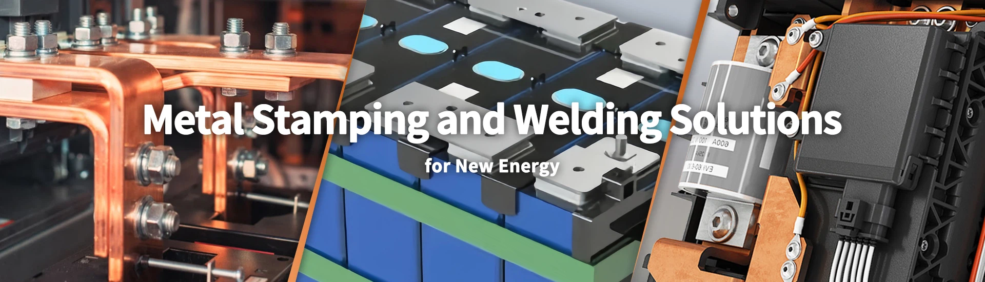
Storage Battery Pack Manufacturer for LFP Energy Storage Systems
Xiamen Apollo supplies storage battery packs and related battery components for residential, commercial, and industrial energy storage applications. Its product range includes LFP battery solutions, 280Ah and 314Ah product categories, aluminum battery enclosures, and cover plates. Product selection is based on rated capacity, voltage configuration, installation conditions, and the electrical requirements of the intended ESS application.
For OEM projects, Apollo supports drawing review, component selection and manufacturing coordination. Battery pack specifications can be evaluated alongside enclosure dimensions, terminal interfaces, copper busbar connections, and insulation requirements. Buyers can submit technical drawings and electrical specifications for a preliminary DFM review, component assessment, and quotation based on the confirmed supply scope.
Request a Factory Direct Quote
Explore Our Storage Battery Pack Product Catalog
Compare available battery pack configurations, LFP cell products, and related enclosure components for different energy storage applications.
-
![Modular Energy Storage For C&I]()
Modular Energy Storage For C&I
Add to Inquiry -
![Grid-connected Industrial Storage Systems]()
Grid-connected Industrial Storage Systems
Add to Inquiry -
![Battery Energy Storage]() Add to Inquiry
-
![Industrial Energy Storage]() Add to Inquiry
-
![Commercial Energy Storage]() Add to Inquiry
-
![Battery Management System BMS]() Add to Inquiry
-
![Battery-based Energy Storage]() Add to Inquiry
-
![Commercial And Industrial Storage Systems]()
Commercial And Industrial Storage Systems
Add to Inquiry -
![Solar Energy Storage Systems Lithium Batteries Pack]()
Solar Energy Storage Systems Lithium Batteries Pack
Add to Inquiry -
![C&I Storage Systems]() Add to Inquiry
-
![BESS For Commercial Use]() Add to Inquiry


Material Standards, Tooling & Forming Processes
Energy storage battery pack components must meet the mechanical, dimensional, and environmental requirements of the target assembly. Depending on the design, metal parts may include aluminum housings, battery covers, mounting brackets, internal support plates, copper busbars, and welded connection assemblies. Each component requires a material and process specification that reflects its position and function within the pack.
Aluminum Structural Components
Aluminum alloys such as 3003 and 5052 may be considered for formed housings, covers and support components, subject to the required strength, corrosion resistance, formability and joining method. Alloy selection should account for wall thickness, draw depth, corner radii and the dimensional changes associated with forming.
Deep drawing can produce enclosure features with controlled profiles, while progressive stamping and multi-stage forming are suitable for repeatable brackets, plates and mounting components. Tooling development should address springback, thinning, wrinkling, burr direction, and the effect of welding on the finished geometry.
Where a component interfaces with battery modules or a cooling assembly, datum references and critical-to-quality dimensions should be identified before tooling release. This reduces the risk of cumulative dimensional variation during pack assembly.
Copper Connections and Current-Carrying Parts
Copper busbars and interconnects are selected according to the electrical load, available installation space, terminal geometry, and thermal conditions. C1100 copper or equivalent specified grades can be evaluated for applications requiring high electrical conductivity. A nominal conductivity value of 100% IACS should only be stated when supported by the material grade and applicable test evidence.
Busbar sizing must consider current, conductor cross-section, conductor length, ambient temperature, enclosure conditions, joint resistance, and cooling. For laminated configurations, conductor spacing and insulation thickness also affect electrical clearance and parasitic inductance.
Battery Pack Component Specifications
| Parameter | Typical engineering consideration | Verification method |
| Aluminum housing material | 3003, 5052 or drawing-specified alloy | Material certificate and incoming inspection |
| Copper conductor material | C1100 or drawing-specified copper grade | Material certificate and conductivity verification where required |
| Forming process | Deep drawing, progressive stamping or multi-stage forming | First-article and in-process inspection |
| Critical dimensions | Defined by drawing and assembly interfaces | Optical measurement, gauges, or CMM |
| Structural joining | Resistance welding, laser welding, or specified mechanical fastening | Joint inspection and mechanical testing |
| Busbar conductivity | Specified by material grade and electrical design | Material verification or conductivity testing |
| Insulation system | Defined by voltage, temperature and environmental requirements | Insulation resistance and dielectric testing where applicable |
| Enclosure protection | Defined by the complete enclosure design and intended installation | Applicable ingress protection testing |
The table describes engineering parameters to be established for each component. Actual material grades, dimensional tolerances, and test limits must be confirmed against the approved drawing and customer specification.
For related battery enclosure requirements, see Aluminum Battery Case.
Tooling and Dimensional Control
Forming feasibility: Check minimum bend radii, draw depth, wall thickness, and local material strain before releasing the tool design.
Springback compensation: Account for alloy, temper, thickness, and forming direction when establishing the final geometry.
Welding distortion: Define fixture locations and inspection datums to control positional changes after joining.
Interface dimensions: Verify mounting holes, terminal positions, sealing surfaces, and module support features against the assembly drawing.
Production consistency: Establish inspection frequency, tool maintenance intervals, and reaction plans for out-of-tolerance parts.
For projects requiring multiple stamped and welded components, a drawing-based DFM review should evaluate both individual part manufacturability and the effect of dimensional variation on final assembly.
Advanced Joining, Insulation & Surface Treatments
Electrical and structural joints inside an energy storage battery pack serve different functions. Current-carrying connections require controlled electrical resistance and stable mechanical retention, while structural joints must withstand the specified static loads, vibration and thermal cycling.
Copper Busbar and Terminal Joining
Resistance welding, laser welding, brazing and mechanical fastening may be suitable depending on the conductor material, thickness, joint configuration and required production rate. The process must be selected according to the drawing and validated against the required electrical and mechanical performance.
For copper-to-aluminum connections, laser welding requires careful control of energy input, joint geometry and the formation of brittle intermetallic compounds. Where applicable, joint cross-sections, tensile or pull-off tests, and electrical resistance measurements can be used to evaluate process consistency.
For high-current assemblies, the quality plan should define the resistance measurement method, test current, contact configuration, and acceptance limit. Results should be interpreted alongside temperature-rise performance under the intended operating conditions.
Insulation and Electrical Separation
Battery pack components may use insulating films, molded insulating parts, coated metal surfaces or laminated busbar structures. Material selection depends on working voltage, transient voltage, temperature, chemical exposure, mechanical abrasion and the required service life.
The electrical design should specify clearance, creepage distance, dielectric withstand voltage, and insulation resistance according to the applicable system requirements. Insulation performance must be assessed on the actual material or assembled component using the appropriate test conditions.
Surface Protection and Corrosion Control
Aluminum housings and steel mounting parts may require anodizing, conversion coating, powder coating, or another specified finish. Copper busbars may use tin, nickel, or silver plating where the contact interface and operating environment justify it.
Surface treatment specifications should identify coating type, thickness where applicable, substrate preparation, coverage requirements and acceptance criteria. For enclosure parts, coating and sealing interfaces should be evaluated together to avoid damage during assembly or loss of environmental protection.
Process Validation Requirements
| Process | Main control parameters | Recommended validation |
| Copper busbar joining | Joint geometry, energy input or fastening torque | Electrical resistance and mechanical integrity |
| Copper-to-aluminum laser welding | Heat input, fusion zone, and material compatibility | Cross-section analysis and specified mechanical tests |
| Insulation application | Material thickness, coverage, and edge protection | Dielectric withstand and insulation resistance |
| Metal surface finishing | Coating specification, substrate preparation, and coverage | Coating inspection and applicable corrosion tests |
| Enclosure sealing | Seal design, compression, and joint continuity | Leakage or ingress protection testing where required |
For related current-carrying components, review the Copper Busbar for the Battery Pack.
Request Custom Technical Evaluation
Quality Control & Certifications at Apollo
Quality control for energy storage battery pack components should cover incoming materials, forming operations, joining processes, dimensional inspection, and final shipment. The inspection plan must be specific to the component's function rather than relying on a single general-purpose checklist.
Dimensional and Material Inspection
Incoming material checks can verify alloy designation, thickness, surface condition, and the required material documentation. During forming and assembly, optical measurement systems, calibrated gauges and CMM equipment may be used to verify critical dimensions where suitable for the component geometry.
For housings and support structures, inspection should focus on mounting locations, flatness, hole positions, sealing interfaces and post-weld distortion. For busbars, the plan should cover conductor dimensions, terminal-hole geometry, bend positions and contact surfaces.
Electrical and Mechanical Verification
Where the supplied component has an electrical function, the applicable inspection plan may include conductivity verification, joint resistance measurement, insulation resistance testing or dielectric withstand testing. Temperature-rise testing should reproduce defined electrical loading and thermal boundary conditions.
Mechanical testing may include tensile, pull-off, or joint-strength tests according to the connection design. Environmental tests such as thermal cycling, vibration, or corrosion exposure should be selected based on the intended installation and customer qualification plan.
A helium mass spectrometer leak test is relevant only to components with a specified hermetic sealing requirement. It should not be presented as a routine test for every battery pack structural part.
Documentation and Traceability
Apollo identifies IATF 16949 and ISO 9001 among its quality-system credentials. The applicable certification scope and current validity should be confirmed before publication or customer submission.
For projects requiring PPAP Level 3, the agreed submission package may include:
Process Flow Diagram.
Process Failure Mode and Effects Analysis (PFMEA).
Control Plan.
Material certificates.
Dimensional inspection results.
Measurement system and process capability records, where required.
Applicable performance and validation test results.
PPAP deliverables depend on the customer's requirements and the approved submission scope. CPK values should be reported only when supported by representative production data and an appropriate statistical analysis.
Production Readiness and Delivery Control
Before mass production, the project team should confirm the approved drawing revision, material specification, inspection plan, packaging method and traceability requirements. For repeat orders, tooling maintenance and process monitoring help control dimensional drift and maintain consistency between production batches.
Packaging should protect formed surfaces, terminal interfaces and coated parts from deformation, contamination and transport damage. Delivery planning should account for tooling readiness, sample approval, production capacity and the customer's forecast.
Frequently Asked Questions
Q: 1. What metal components can be supplied for an energy storage battery pack?
A: Depending on the approved product scope, components may include aluminum housings, covers, mounting brackets, internal support plates, copper busbars and welded metal assemblies. The available manufacturing scope should be confirmed from the drawing and project requirements before quotation.
Q: 2. How should copper busbars be specified for an ESS battery pack?
A: The specification should include conductor material, cross-section, length, terminal geometry, surface finish and installation constraints. Current capacity and temperature rise must be evaluated against operating current, ambient temperature, enclosure conditions, joint resistance, and cooling. Material conductivity alone does not establish the allowable current rating.
Q: 3. What dimensional tolerances are suitable for battery pack structural components?
A: Tolerances should be assigned according to assembly function, manufacturing method, and measurement capability. Mounting holes, sealing surfaces, and module interfaces may require tighter controls than non-functional surfaces. Final tolerances should be documented on the approved drawing and verified using suitable calibrated inspection equipment.
Q: 4. Can Apollo provide complete energy storage battery packs or only metal components?
A: This depends on Apollo's confirmed product and engineering scope. The page primarily addresses metal structural components and electrical connection parts. Customers requiring cells, BMS, thermal management, enclosure integration, or complete battery pack qualification should confirm those capabilities and responsibilities before placing an order.
Request an Energy Storage Battery Pack Component Quote
Provide your battery pack drawings and engineering requirements to begin a manufacturing review. Apollo can assess the manufacturability of specified metal housings, support brackets, copper connections, and welded assemblies according to the agreed product scope.
Submit 2D drawings in .DWG or PDF format, 3D CAD files in STEP format, or a technical specification containing material grades, critical dimensions, joining methods, surface finishes, and annual demand. Include electrical load requirements, insulation criteria, and environmental conditions where relevant.
The initial review can identify forming constraints, joining considerations, critical inspection dimensions, and documentation requirements before tooling or production release. A preliminary DFM review and quotation within 24 hours may be arranged for complete inquiries, subject to drawing complexity and engineering workload.
We're well-known as one of the leading storage battery pack manufacturers and suppliers in China. Please feel free to buy high quality storage battery pack at competitive price from our factory. For more information, contact us now.
