

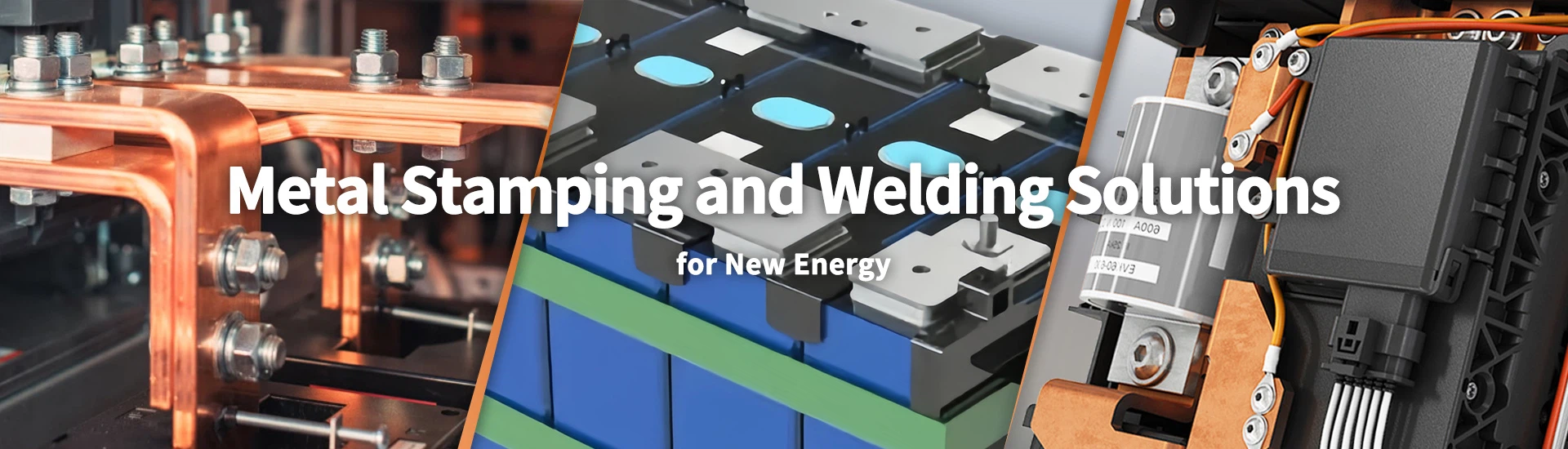
Direct-Factory Busbar Manufacturer for Copper, Laminated, and Flexible Busbar Solutions
Xiamen Apollo Stamping Welding Technology manufactures customized busbars for EV battery systems, energy storage equipment, power electronics, and industrial electrical applications. Our production integrates precision stamping, CNC machining, welding, and insulation processes using high-conductivity copper materials such as C1100 and T2 copper with conductivity up to 100% IACS.
Our engineering team supports drawing review, DFM optimization, and mass production with controlled dimensions, surface treatment options, and complete quality documents. From prototype development to high-volume supply, Apollo provides OEM busbar manufacturing based on customer electrical parameters, mechanical requirements, and PPAP Level 3 documentation.
Request a Factory Direct Quote
Explore Our Busbar Product Catalog
Select suitable copper, laminated, flexible, and insulated busbar solutions designed for high-current electrical connection systems.
-
![Capacitor Stainless Steel Cans]()
Capacitor Stainless Steel Cans
Add to Inquiry -
![Stainless Steel Cans For High Voltage Film Capacitor]()
Stainless Steel Cans For High Voltage Film Capacitor
Add to Inquiry -
![Steel Stainless Can]() Add to Inquiry
-
![Progressive Die Stamping]() Add to Inquiry
-
![Carbon Steel Metal Stamping]() Add to Inquiry
-
![Stainless Steel Can Of Power Capacitor]()
Stainless Steel Can Of Power Capacitor
Add to Inquiry -
![Stainless Steel Can For Power Capacitor]()
Stainless Steel Can For Power Capacitor
Add to Inquiry -
![Steel Capacitor Can]() Add to Inquiry
-
![Stainless Steel Shell for Rail Transit Capacitor]()
Stainless Steel Shell for Rail Transit Capacitor
Add to Inquiry -
![Stainless Steel 304 Case for Capacitor]()
Stainless Steel 304 Case for Capacitor
Add to Inquiry -
![Capacitor Stainless Steel Can]() Add to Inquiry
-
![Industrial Machinery U-nut U-clip Combination]()
Industrial Machinery U-nut U-clip Combination
Add to Inquiry


Material Standards, Tooling & Forming Processes
Steel welding parts are specified according to the material grade, thickness, load path, operating environment, and dimensional requirements of the finished assembly. Carbon steel may be suitable for structural brackets, mounting supports, equipment frames and load-bearing components. Stainless steel may be selected where corrosion resistance, cleaning conditions or process compatibility requires it. The exact grade should be confirmed against the drawing and applicable material standard.
Before production, the engineering review should establish the relationship between the formed component and its welded joints. Stamped steel parts may require controlled blanking, bending, hole positioning, and edge preparation before joining. Cut and formed components should maintain adequate fit-up to avoid excessive weld gaps, uneven joint penetration, or unnecessary filler material.
For assemblies containing multiple parts, fixture design establishes the relative position of mating surfaces and helps control movement during welding. Datum references should be defined before inspection so that weld shrinkage, angular distortion, and hole-position variation can be evaluated against the finished assembly requirements.
Material and Manufacturing Considerations
Carbon steel: Confirm grade, thickness, strength requirements, and weldability before selecting the welding procedure.
Stainless steel: Evaluate grade compatibility, heat input, distortion, and the surface condition required after welding.
Joint design: Define butt, lap, fillet, or other joint configurations according to load direction, accessibility, and drawing requirements.
Fixture and clamping: Control component location and movement while allowing a practical welding sequence.
Post-weld machining: Consider where mounting holes, locating faces, or mating dimensions require tighter control than the welding process alone can maintain.
Steel Welding Part Specifications Table
| Parameter | Specification basis | Inspection or verification |
| Material grade | Carbon steel or stainless steel grade specified by drawing | Material certificate and grade verification |
| Material thickness | Drawing-defined sheet or plate thickness | Calibrated thickness gauge |
| Joint configuration | Butt, lap, fillet, or specified welded joint | Drawing review and weld inspection |
| Weld size and length | Defined by drawing or approved weld specification | Weld gauges and visual inspection |
| Dimensional tolerance | Drawing-defined tolerances; ±0.01 mm only for validated features and processes | CMM, optical measurement, or calibrated gauges |
| Hole position and mounting interface | Datum-based drawing requirements | CMM or suitable dimensional gauges |
| Surface condition | As-welded, cleaned, coated, or otherwise specified | Visual inspection and coating checks |
| Corrosion protection | Specified coating, plating or passivation system where applicable | Process records and relevant coating tests |
| Mechanical performance | Defined load, strength, or joint acceptance requirements | Mechanical testing where required |
The table defines the information required for engineering review. It does not imply that every steel welded part uses the same material, tolerance or testing regime.
Tooling and Dimensional Control
The manufacturing route should be selected according to annual demand, component complexity and the number of welded features. Progressive stamping can support repeat production of suitable small parts, while laser cutting, press forming and dedicated fixtures may be more appropriate for other geometries.
For components with close-fitting interfaces, the inspection plan should identify critical-to-quality dimensions and their measurement datums. If a welded assembly contains mounting holes or machined locating faces, the inspection sequence should distinguish pre-weld dimensions from final post-weld dimensions.
For combined fabrication projects, review Precision Metal Stamping Parts to assess whether stamping and welding can be planned within one manufacturing route.
Advanced Joining, Weld Integrity & Surface Treatments
The welding method for a steel assembly should match the material grade, thickness, joint geometry, required production rate, and acceptance criteria. MIG/MAG welding may be suitable for many carbon steel fabrications, while TIG welding can be considered where control of the weld pool and joint appearance is important. Resistance welding may suit compatible sheet-metal assemblies with accessible contact surfaces. The final method should be confirmed during process review.
Welding Process Selection
| Welding method | Potential applications | Main process controls |
| MIG/MAG welding | Steel frames, brackets and fabricated assemblies | Wire feed, current, voltage, travel speed and shielding gas |
| TIG welding | Selected thin sections, precision joints and stainless steel components | Current, travel speed, filler selection and shielding |
| Resistance welding | Suitable for overlapping sheet-metal joints | Electrode force, current, weld time and electrode condition |
| Laser welding | Compatible geometries requiring localized heat input | Power, travel speed, focus position, joint fit-up and penetration |
| Robotic welding | Repeat production with consistent joint accessibility | Program path, fixture location, process parameters and inspection feedback |
A stable welding process depends on fit-up, surface cleanliness, consumable selection and controlled heat input. Excessive heat can increase distortion, while insufficient energy or poor joint preparation can result in incomplete fusion. Process parameters should be qualified against the relevant material and joint design rather than transferred between dissimilar part configurations without validation.
Weld Inspection and Surface Protection
Inspection requirements should be set according to the consequences of joint failure and the applicable drawing or customer standard. Visual inspection can identify surface discontinuities such as visible cracks, undercut, excessive spatter, and profile irregularities. Weld gauges can verify specified fillet dimensions. Where the joint risk or specification requires it, penetrant testing, magnetic particle testing, ultrasonic testing or radiographic inspection may be considered according to material, geometry and defect type.
Post-weld surface treatment may include cleaning, deburring, coating, painting or another specified corrosion protection process. Stainless steel assemblies may require a different surface restoration procedure from carbon steel parts. Coating selection should reflect the service environment, exposure to moisture or chemicals, and any required adhesion or corrosion test.
For components installed outdoors, corrosion protection must be evaluated as a complete system: substrate preparation, weld condition, coating coverage, edge protection, and drainage geometry can all affect durability.
Request Custom Technical Evaluation
Quality Control & Certifications at Apollo
Quality control for steel welding parts should link material identity, fabrication parameters, weld acceptance and final dimensional results. The inspection plan can be developed from the drawing, product risk, and customer-specific requirements, with particular attention to load-bearing joints, mounting interfaces, and dimensions affected by welding distortion.
Incoming material checks should verify the specified grade and thickness. In-process controls may include joint preparation, fixture position, welding parameters and weld sequence. Final inspection should verify critical dimensions, weld appearance, and surface treatment requirements. Where the application calls for more detailed verification, additional non-destructive examination or mechanical testing should be agreed upon before production release.
Recommended Quality Control Plan
| Inspection stage | Control item | Typical evidence |
| Incoming material | Grade, thickness and condition | Material certificate and incoming inspection record |
| Pre-weld preparation | Edge condition, joint gap and fit-up | First-piece check and process inspection |
| Welding | Approved parameters and joint sequence | Process records where applicable |
| Weld acceptance | Surface discontinuities and specified weld dimensions | Visual inspection and weld-gauge records |
| Dimensional inspection | Mounting holes, interfaces and final geometry | Dimensional inspection report |
| Non-destructive testing | Selected welds where required by drawing or specification | Applicable NDT report |
| Surface treatment | Coverage, finish and specified coating requirements | Visual inspection and coating records |
| Final release | Drawing compliance, quantity, identification and packaging | Final inspection and lot traceability records |
Apollo's quality-system credentials and the scope of their application should be confirmed against current certificates before publication.
Where IATF 16949:2016 or ISO 9001 requirements apply to a specific production site and process, the relevant certification scope should be verified.
For automotive projects requiring PPAP Level 3, documentation can be planned according to customer requirements and the applicable submission level. The package may include a process flow diagram, PFMEA, control plan, material certificates, dimensional results, and process capability studies where required and supported by production data.
CMM measurement, optical measurement, and weld inspection methods should be assigned according to feature geometry and acceptance criteria. A quoted instrument resolution or measurement capability should not be treated as proof that every dimension can be manufactured or verified to the same tolerance.
Production Repeatability and Delivery
For repeat orders, the manufacturing plan should identify the approved drawing revision, material specification, welding procedure, fixture configuration, and final inspection criteria. Any change affecting fit-up, weld parameters, coating or critical dimensions should be evaluated through the agreed change-control process.
Packaging should protect mounting faces, threaded features and coated surfaces against impact, abrasion and moisture during transport. For projects with defined lot traceability, labels and inspection records should link finished assemblies to the relevant production batch.
Frequently Asked Questions
Q: 1. Which steel grades can be used for custom steel welding parts?
A: Carbon steel and stainless steel may be suitable, depending on load requirements, corrosion exposure, material thickness, and the specified welding process. The exact grade should be stated on the drawing or material specification. Weldability and any preheating or post-weld requirements must be evaluated for the selected material.
Q: 2. How can welding distortion be controlled on precision steel assemblies?
A: Distortion control starts with suitable joint design, consistent fit-up, fixture positioning, and a qualified welding sequence. Heat input and weld order should be selected for the material thickness and assembly geometry. Final inspection should verify mounting holes, datum relationships, and other critical dimensions after welding and any required machining.
Q: 3. What inspection methods are available for steel welded components?
A: Inspection may include visual examination, weld-gauge measurement, and dimensional checks using calibrated gauges, optical systems, or CMM equipment. Depending on joint design and risk, magnetic particle, penetrant, ultrasonic, or radiographic testing may be specified. The method and acceptance criteria should be agreed upon before production.
Q: 4. Can Apollo manufacture steel welding parts to a customer drawing?
A: Projects can be reviewed using 2D drawings, 3D CAD models, material requirements, annual volume, and inspection specifications. The review should establish the manufacturing route, fixture needs, joining method, critical dimensions, and quality documents. Feasibility, achievable tolerances, lead time, and quotation scope can then be confirmed for the specific component.
Request a Custom Steel Welding Part Quote
Send your 2D drawing in .DWG or PDF format, your 3D model in STEP format, or your component specification to Apollo for a manufacturing review.
To evaluate the project accurately, include the steel grade, material thickness, joint configuration, critical dimensions, surface treatment, annual demand, and any weld inspection or mechanical load requirements. If PPAP documentation or other customer-specific quality records are required, state these requirements at the quotation stage.
Apollo can review the proposed fabrication route, welding process, fixture requirements, and dimensional inspection plan before confirming feasibility and pricing. A preliminary DFM review and quotation target within 24 hours may be arranged for complete inquiries, subject to drawing complexity and engineering workload.
We're well-known as one of the leading steel welding part manufacturers and suppliers in China. Please feel free to buy high quality steel welding part at competitive price from our factory. For more information, contact us now.
