


Custom Steel Stamping Parts Manufacturer for Industrial and Automotive Applications
Xiamen Apollo Stamping Welding Technology manufactures custom steel stamping parts from carbon steel, stainless steel, and specified alloy steel sheets. Production processes include blanking, piercing, bending, deep drawing, and progressive die stamping. Material selection is based on required strength, formability, sheet thickness, corrosion exposure, and finished-part geometry.
Our engineering team reviews 2D drawings and 3D CAD models to evaluate forming feasibility, tooling structure and critical dimensions before production. We support prototype development, tooling manufacture, and repeat production, with inspection requirements defined according to component drawings and customer quality specifications.
Request a Factory Direct Quote
Explore Our Steel Stamping Parts Product Catalog
Review our carbon steel, stainless steel, and deep-drawn components to identify suitable parts for your application and production requirements.
-
![Carbon Steel Sheet Metal Stamping]()
Carbon Steel Sheet Metal Stamping
Add to Inquiry -
![Carbon Steel Stampings]() Add to Inquiry
-
![Stamping Steel Parts]() Add to Inquiry
-
![Custom Metal Stamp For Steel]() Add to Inquiry
-
![Custom Stainless Steel Stamping Parts]()
Custom Stainless Steel Stamping Parts
Add to Inquiry -
![Sheet Metal Pressing]() Add to Inquiry
-
![Sheet Metal Stamping Part]() Add to Inquiry
-
![Deep Drawn Metal Stamping]() Add to Inquiry
-
![Sheet Metal Stamping Parts]() Add to Inquiry
-
![Sheet Metal Stamping Die]() Add to Inquiry
-
![Custom OEM Carbon Steel Zinc Coated Metal Stamping]()
Custom OEM Carbon Steel Zinc Coated Metal Stamping
Add to Inquiry -
![Strength Metal Stamping Part]() Add to Inquiry
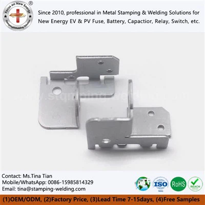


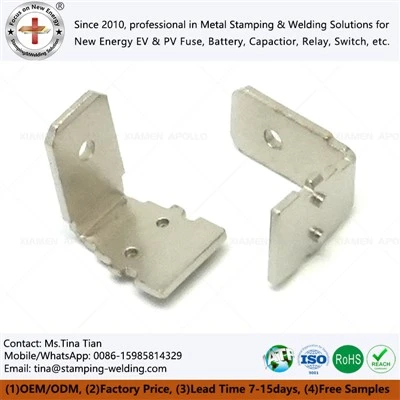
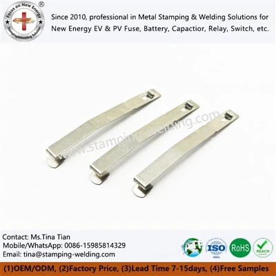
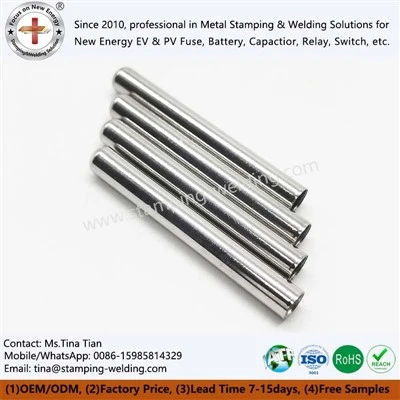
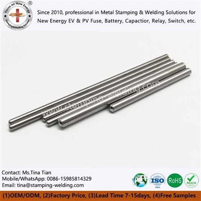

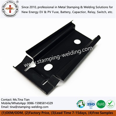


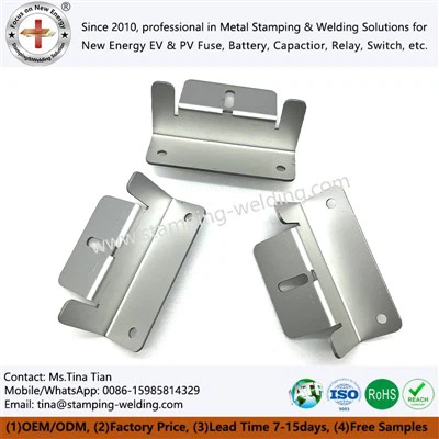
Material Standards, Tooling & Forming Processes
Steel stamping performance depends on the interaction between material grade, sheet thickness, mechanical properties, rolling direction, and die geometry. Carbon steel is commonly selected for structural brackets, mounting plates, support components, and formed hardware.
Galvanized steel can provide corrosion protection through its zinc coating, while stainless steel is considered when the application requires a different balance of corrosion resistance, strength, and surface condition.
Material selection should start with the specified grade and applicable material standard. Low-carbon steels are often suitable for drawing and bending operations, whereas higher-strength grades may require larger forming radii, adjusted die clearances and more detailed springback compensation. Stainless steel also requires attention to work hardening, galling, and surface marking during forming.
Apollo's steel stamping process can integrate blanking, piercing, bending, embossing and deep drawing according to the part geometry.
Progressive dies are appropriate for parts with repeated features and stable production volumes. For deeper or more complex shapes, draw depth, corner radii, blank-holder force, and material flow must be reviewed to reduce wrinkling, splitting, and local thinning.
Tooling design should also establish the relationship between critical dimensions and functional assembly interfaces. For example, a mounting bracket may require controlled hole spacing and bend angles, while a drawn housing may require profile accuracy, wall thickness consistency and a defined edge condition.
Steel Stamping Parts — Technical Specifications
| Parameter | Specification basis | Engineering consideration |
| Material | Carbon steel, galvanized steel or stainless steel | Confirm grade and applicable material standard |
| Sheet thickness | Defined by approved drawing | Affects forming force, stiffness, and springback |
| Tensile and yield properties | Material certificate and specified grade | Determine load capacity and forming behavior |
| Forming method | Blanking, piercing, bending, drawing or progressive stamping | Selected according to geometry and production volume |
| Dimensional tolerance | Drawing-defined; ±0.01 mm only where process capability is verified | Depends on feature type, material, and tooling |
| Hole and slot geometry | Drawing-defined diameter, position and profile | Verify assembly fit and edge distance |
| Burr height | Customer-defined acceptance limit | Depends on die clearance, tool condition, and material |
| Surface treatment | Galvanizing, zinc plating, powder coating, or other specified finish | Match substrate and coating to the service environment |
| Inspection | Optical measurement, gauges, CMM, or other suitable methods | Select according to component geometry and tolerance |
The table defines the main engineering inputs rather than universal product limits. Actual material grades, tolerances and inspection methods must be confirmed for each component.
Progressive Die Design and Dimensional Stability
A stable stamping process begins with a die layout that considers material utilization, station sequence, part orientation and critical feature formation. Punch-to-die clearance must be selected for the specified material and thickness; excessive clearance can increase burrs, while insufficient clearance may increase cutting force and tool wear.
For formed parts, springback compensation should be established through material data, tooling trials and dimensional measurement. The appropriate correction depends on steel grade, tensile properties, thickness and bend geometry. A nominal tolerance should not be promised until the production process has demonstrated that it can hold the requirement consistently.
Where components require close positional relationships, the drawing should identify datum references and functional dimensions. This allows inspection results to reflect how the part fits into the customer's assembly rather than relying on isolated measurements alone.
For related products, see Precision Stamped Steel Parts.
Advanced Joining, Corrosion Protection & Surface Treatments
Steel stamping parts may be supplied as formed components or integrated into welded and assembled structures. The joining method and surface treatment should be specified together because welding heat, coating damage, and post-process deformation can affect the finished component.
Resistance welding can be used for suitable sheet-metal joints when electrode force, current, weld time and surface condition are controlled. Laser welding may be considered for joints requiring localized heat input, subject to material thickness, joint design, and production validation. For load-bearing assemblies, joint geometry and mechanical acceptance criteria should be established before production approval.
Surface Treatment Selection
Surface protection should be matched to the base material and operating environment.
Galvanized steel: Zinc coating provides sacrificial corrosion protection. Forming damage, exposed edges, and coating condition should be considered when defining acceptance requirements.
Zinc-plated carbon steel: Electroplated zinc may be suitable for components requiring a controlled coating system. Coating thickness and any required passivation should be specified.
Stainless steel: Corrosion resistance depends on alloy grade, surface condition, and exposure environment. Additional coating is not automatically required.
Powder-coated steel: The coating system should define pretreatment, film thickness, adhesion, and curing requirements.
Post-stamping coating: If parts are stamped before coating, edge coverage and any corrosion-sensitive contact areas should be included in the process review.
Salt spray testing can help compare corrosion behavior under a defined test procedure, but the result does not directly predict service life in every field environment. The required test method, exposure duration, and acceptance criteria should be stated in the drawing or product specification.
Joining and Surface Treatment Controls
| Process | Main control variables | Suggested verification |
| Resistance welding | Electrode force, current, weld time, and electrode condition | Weld appearance and mechanical test as specified |
| Laser welding | Joint gap, power, travel speed, and heat input | Weld profile and mechanical testing where required |
| Zinc plating | Coating thickness, coverage and surface condition | Coating thickness measurement |
| Powder coating | Pretreatment, film thickness and curing conditions | Film thickness and adhesion testing |
| Corrosion testing | Test method, exposure duration and acceptance criteria | Test report against the agreed specification |
For welded components, a visually acceptable seam does not alone establish joint strength. For coated parts, a measured coating thickness does not alone establish corrosion resistance. Both must be assessed against the applicable requirements and test methods.
Manufacturing Route for Custom Steel Stampings
A typical project route includes drawing review, material specification confirmation, tooling design, first-article production, dimensional approval, process validation, and batch production. If joining or coating follows stamping, the inspection plan should identify which dimensions are checked before and after those operations.
This sequence helps identify process-related variation before mass production. It also establishes clear acceptance criteria for tooling changes, material substitutions, and revisions to the approved drawing.
Request Custom Technical Evaluation
Quality Control & Certifications at Apollo
Steel stamping quality control should verify the material, formed geometry, edge condition, and surface finish at the stages where defects can be detected and corrected efficiently.
Incoming inspection can confirm material grade, thickness, and the supplied material certificate. During stamping, in-process checks can monitor critical dimensions, burr formation, cracks, wrinkles and tooling wear. For deep-drawn components, inspection may also cover profile dimensions and visible thinning or surface damage.
Optical measurement systems, calibrated gauges and CMM equipment can be selected according to part size, geometry and tolerance. The inspection plan should identify the datum scheme, measurement locations, sampling frequency and acceptance criteria. Tight tolerances should be supported by measurement-system suitability and demonstrated process capability, not by machine specifications alone.
Apollo's quality-system credentials and the scope applicable to this product line should be verified before publication. Where a project requires automotive documentation, PPAP Level 3 deliverables may be agreed with the customer, subject to the applicable program requirements and confirmed capability.
Recommended Inspection Plan for Steel Stamping Parts
| Stage | Inspection focus | Evidence or record |
| Incoming material | Grade, thickness, material condition and coating where applicable | Material certificate and incoming inspection record |
| Tooling trial | Critical dimensions, bend angles, and forming defects | First-article dimensional report |
| In-process stamping | Hole positions, profile dimensions, burrs and visible cracks | In-process inspection record |
| Deep drawing | Profile accuracy, wrinkling, splitting and surface damage | Dimensional and visual inspection |
| Surface treatment | Coating type, thickness, coverage and adhesion where specified | Coating inspection or test report |
| Final inspection | Drawing compliance, quantity, packaging and part identification | Final inspection record |
| Automotive program | Applicable process documentation and capability evidence | Customer-agreed PPAP submission |
Process Capability and Change Control
For critical-to-quality features, Cpk analysis can help assess whether a stable process operates within the specified tolerance limits. Its interpretation depends on the sample size, data distribution, process stability, and measurement system. A Cpk value should therefore be reported only when supported by an appropriate study.
Changes to material grade, material supplier, die design, forming parameters or coating process should be evaluated against their potential effect on fit, strength, corrosion resistance and dimensional consistency. Where required by the customer, changes should be documented and approved before implementation.
Packaging and Batch Traceability
Stamped steel parts should be packaged to prevent deformation, edge damage, corrosion and surface scratches during storage and international transport. Protective separators, moisture control, and anti-rust measures should be selected according to material type, coating system, and shipping conditions.
For repeat production, lot identification should link finished components to relevant material and inspection records. This supports defect investigation and helps maintain consistency when orders are produced across multiple batches.
Frequently Asked Questions About Steel Stamping Parts
Q: 1. Which steel grade is suitable for custom steel stamping parts?
A: The correct grade depends on forming depth, required strength, corrosion exposure, and component geometry. Low-carbon steel is commonly considered for formed structural components, while stainless steel may suit more corrosive environments. Final selection should reference the required material standard, mechanical properties, and drawing specification.
Q: 2. Can steel stamping parts achieve a tolerance of ±0.01 mm?
A: A ±0.01 mm tolerance may be feasible for selected features under controlled conditions, but it should not be applied universally to every stamped part. Feasibility depends on material thickness, die design, feature geometry, process stability, and measurement capability. Critical dimensions should be reviewed and validated during tooling trials.
Q: 3. How can burrs and springback be controlled during steel stamping?
A: Burr formation is influenced by die clearance, cutting-edge wear, and material thickness. Springback depends on material properties, bend geometry, and forming conditions. Appropriate tooling design, process trials, scheduled die maintenance, and dimensional inspection help control both issues. Acceptance limits should be defined for the specific part drawing.
Q: 4. Which surface treatment is appropriate for steel stamping parts used outdoors?
A: Selection depends on base material, moisture exposure, corrosive agents, expected service conditions, and appearance requirements. Galvanized steel, zinc plating, and powder coating provide different protection mechanisms. Specify the coating system, edge protection requirements, and applicable corrosion test criteria rather than selecting a finish based on appearance alone.
Request a Custom Steel Stamping Parts Quote
The manufacturability of a stamped steel component depends on material properties, sheet thickness, forming geometry, tooling design, and the required dimensional tolerances. Early drawing review helps identify potential forming risks and establish a suitable production and inspection plan.
Submit your 2D drawings in .DWG or PDF format, 3D CAD models in STEP format, or a technical specification containing the steel grade, thickness, critical dimensions, annual demand, and surface treatment requirements.
Apollo can review the supplied information for forming feasibility, tooling considerations, inspection requirements, and quotation scope. A preliminary DFM review within 24 hours can be requested for complete submissions; actual response time depends on drawing complexity and engineering workload.
We're well-known as one of the leading steel stamping parts manufacturers and suppliers in China. Please feel free to buy high quality steel stamping parts at competitive price from our factory. For more information, contact us now.
