Busbar for Power Capacitor Selection Guide: Addressing Industry Pain Points, Aligning with Industry Standards, and Precisely Adapting to High-Voltage Systems
Mar 14, 2026
product definition
The new energy vehicle busbar is a multi-layer composite conductive connector used in the power electronic system of electric vehicles. It is mainly used to connect the DC support capacitor (DC-Link Capacitor) and the power module (IGBT/SiC module) to achieve low-impedance transmission of large current and stable distribution of the busbar voltage. The busbar usually adopts a multi-layer copper plate or aluminum plate laminated structure, and the layers are separated by insulating materials to form a low-inductance, high-reliability electrical connection path. IGBT Bus Bar is the IGBT busbar, which is specially used to connect IGBT power modules and DC support capacitors. It is the core conductive component in the electric vehicle inverter. The design needs to simultaneously meet low stray inductance (to reduce switch overvoltage), high current carrying capacity (hundreds of amps) and good heat dissipation performance. EV Laminated Busbars are electric vehicle laminated busbars. They use a multi-layer laminated structure to stack the positive and negative copper bars together, tightly coupling the positive and negative current paths, and using the mutual inductance effect to reduce the stray inductance of the loop to a low level.
The application of laminated busbars greatly simplifies the internal wiring of the inverter, while improving the power density and reliability of the system. Busbar for DC-Link Capacitor is a DC support capacitor busbar, which is specially used to connect DC-Link capacitors and the DC bus of power modules. The DC-Link capacitor plays a voltage support and filtering role in the inverter. The busbar serves as a bridge between the capacitor and the power module. Its stray inductance directly affects the voltage spike when the IGBT is turned off. Capacitor Busbar is the collective name for capacitor busbar, covering various forms of conductive connections between film capacitors, electrolytic capacitors and power modules. EV Capacitor Connector Bar is an electric vehicle capacitor connecting bar. It usually refers to a short busbar connecting multiple capacitor units or capacitor banks. The form is relatively simple but the quantity is large. EV Capacitor Power Distribution Bar is an electric vehicle capacitor power distribution busbar, which is used to distribute DC power from the battery pack to multiple capacitors or power modules to function as a power distribution busbar.
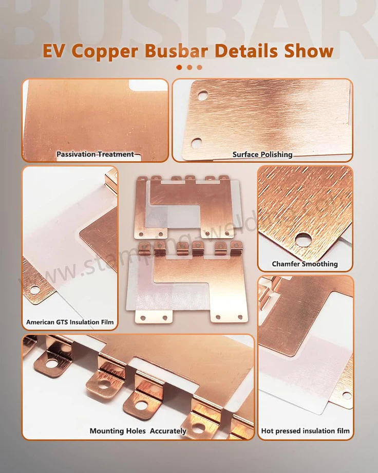
Detailed display
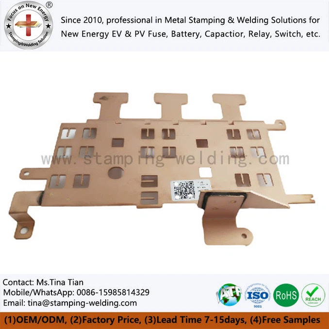
The quality of new energy vehicle busbars is reflected in multiple detailed dimensions from material selection to finished product testing. The first is the control level of stray inductance - place the IGBT Bus Bar on an inductance tester and measure the stray inductance between the positive and negative loops. For electric vehicle inverter applications, the stray inductance of the laminated busbar is usually required to be between 10-30nH (the lower, the better). Excessive stray inductance will cause voltage spikes when the IGBT is turned off, reducing system efficiency and even damaging the power module. Observing the design of the busbar, whether it adopts a laminated structure with tightly coupled positive and negative poles, and whether an inductance offset slot is opened in the current commutation area is an important basis for evaluating the design quality. The second is the flatness and surface quality of the terminal contact surface - for the Busbar for DC-Link Capacitor and EV Film Capacitor Busbar, the flatness of the copper surface in contact with the capacitor terminals and power module terminals should be controlled within 0.1mm. Use a knife-edge ruler or feeler gauge to check the terminal surface. Qualified products should have no warpage or dents visible to the naked eye. The coating surface should be uniform and bright, without oxidation, discoloration or scratches.
The third detail is the edge positioning and creepage distance of the insulation layer - for EV Laminated Busbars, check whether the edge of the insulation layer exceeds the edge of the copper bar to meet the design requirements (usually ≥ 2mm), which is the key to ensuring the creepage distance and electrical clearance. The edges of the insulation layer should be neat, without delamination, bubbles, or damage. At the positive and negative terminal lead-out parts of the busbar, check whether the insulation layer completely covers all conductive surfaces except the terminal contact area. The fourth detail is the bonding strength after lamination - try to peel off the adhesive interface between the insulation layer and the copper bar with your hands or tools, you should feel obvious resistance, and the interface should show a uniform adhesive residue (rather than a smooth copper surface) after peeling off. For the epoxy coating in Insulated Busbar for EV Capacitor, use the cross-hatch method to test the adhesion - draw a 1mm × 1mm grid on the surface of the coating, stick it with tape and then peel it off. The peeling area of the coating should be less than 5%. The fifth detail is the temperature rise performance of the busbar - after the temperature rise has stabilized under continuous power supply at the rated current, measure the temperature of each part of the busbar.
Application industry
The application industries of new energy vehicle busbars are mainly concentrated in the fields of electric vehicle manufacturing, power module packaging, charging infrastructure and industrial inverters. In the electric vehicle manufacturing industry, IGBT Bus Bars and EV Laminated Busbars are key components in electric vehicle inverters (motor controllers). The inverter of each electric vehicle usually contains a set of positive and negative busbars or three-layer busbars (positive pole, negative pole, midpoint). With the rapid development of electric vehicles towards high voltage (800V platform) and high power density, higher requirements have been put forward for the current carrying capacity, heat dissipation performance and low inductance design of the busbar. In the power module packaging industry, Busbar for DC-Link Capacitor is widely used in supporting solutions for power modules (IGBT modules, SiC modules). Power module manufacturers often co-design with busbar suppliers to optimize the match between module terminal layout and busbar interface, thereby reducing voltage spikes when the module is turned off and improving system efficiency.
In the field of charging infrastructure, the EV Capacitor Power Distribution Bar is used in the power modules of DC charging piles. DC charging piles need to convert alternating current into direct current to charge electric vehicles, and their internal rectifier modules and DC-DC modules also require DC-Link capacitors and supporting busbars. The busbars in charging piles need to meet the weather resistance, moisture-proof and dust-proof requirements for outdoor applications. In the field of industrial frequency converters, similar products of EV Film Capacitor Busbar are also widely used in industrial motor drives. Although industrial frequency converters and electric vehicle inverters have different working environment requirements (the industrial environment is relatively mild, but has higher requirements for continuous working life), the basic functions and design principles of the busbars are the same. In the field of battery packs and energy storage systems, Insulated Busbar for EV Capacitor is sometimes used for connections between battery modules and power distribution connections in BMS (Battery Management System). For the small products in the Capacitor Busbar, it is also used in automotive auxiliary power electronic equipment such as on-board chargers (OBC), DC-DC converters, and electric compressor controllers. Although the power level of these devices is lower than that of the main drive inverter, they also require low-inductance busbar connection solutions to ensure electromagnetic compatibility and system efficiency.

FAQ
Q: Why do new energy vehicle busbars use laminated structures? What are the advantages?
A: The laminated structure closely overlaps the positive and negative copper bars through the insulating layer, so that the positive and negative current paths are close to each other. Utilizing the mutual inductance effect, the magnetic fields generated by the positive and negative currents cancel each other out, thereby significantly reducing the loop stray inductance (to 1/10 to 1/50 of traditional cable connections). Low inductance means low voltage spikes when the IGBT is turned off, small switching losses, and less electromagnetic interference. At the same time, the laminated structure also simplifies the internal wiring of the inverter and improves power density.
Q: What are the general requirements for stray inductance of IGBT busbars? How to measure?
A: For electric vehicle inverter applications, the stray inductance of the laminated busbar is usually required to be less than 30nH, and advanced designs can reach 10-15nH. Measurement method: Use an LCR bridge or impedance analyzer to apply a test signal from the DC input end of the busbar and measure the inductance value between the positive and negative loops. When measuring, attention should be paid to installing the busbar on a fixture that simulates the actual installation environment (including the connection with the capacitor) to ensure that the measurement results are close to the actual working conditions.
Q: How to choose between copper busbar and aluminum busbar?
A: The copper busbar has higher conductivity, better weldability, and a thermal expansion coefficient that better matches the power module terminals. It is suitable for main power circuits and occasions with extremely high reliability requirements. Aluminum busbars are light in weight and low in cost, but have low conductivity, difficult welding, and the risk of electrochemical corrosion with copper terminals needs to be noted. At present, the mainstream of the industry is still dominated by copper busbars. Some models with high lightweight requirements are beginning to try aluminum busbars in auxiliary circuits.
Q: What are the connection methods between Busbar for DC-Link Capacitor and IGBT module?
A: There are three main ways: bolt connection; crimp connection (the busbar terminal is designed as an elastic structure and plugged into the IGBT terminal, saving space but the contact pressure needs to be accurately controlled); welding connection. The inverter design needs to be selected according to the actual situation.
contact us
For detailed selection guidelines, technical parameter interpretations, and compliance adaptation solutions for busbar for Power Capacitor, please feel free to contact us for professional technical support.