Comprehensive guide for design and selection of Low Voltage BusBar: from principle to practice
Jan 27, 2026
As the "arterial system" of low-voltage switchgear, the Low Voltage BusBar is the core component of power transmission and distribution, undertaking the important mission of connecting various electrical equipment and safely and reliably distributing power. In low-voltage distribution systems, the design and selection of Copper BusBar directly affect the reliability, safety, and economy of the entire distribution system. Excellent busbar design not only ensures stable system operation and reduces power loss, but also reduces the risk of failure and extends equipment lifespan.
With the rapid development of modern industry and the continuous growth of electricity demand, low-voltage distribution equipment is facing higher performance requirements. As a key core component, the design and selection of Electrical Bus Bar need to comprehensively consider various factors such as electrical performance, mechanical characteristics, thermal performance, and environmental adaptability. This article will comprehensively and deeply analyze the core points and practical methods of low-voltage cabinet Electrical Copper BusBar design and selection, providing systematic and practical professional references for electrical engineers and distribution equipment designers.

The advantages and surface treatment technology of Low Voltage BusBar
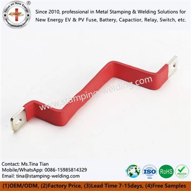
The absolute advantage of copper material: In low-voltage switchgear, Copper Solid Bus Bar material is mainly made of high-quality electrolytic copper, with a copper content of not less than 99.9%, which meets the requirements of relevant industry standards. Despite the existence of alternative materials such as aluminum bars in the market, copper has become the preferred material for the vast majority of low-voltage switchgear busbars due to its superior electrical conductivity (conductivity up to 97% IACS or higher), higher mechanical strength, and superior corrosion resistance.
The Power BusBar is usually manufactured in accordance with the GB/T 5585.1-2018 standard, using rigid hard drawn high conductivity electrolytic copper processing to ensure that the cross-section of the busbar is uniform and consistent throughout its entire length, and can stably withstand continuous load currents. Compared to aluminum, although BusBar Copper has a slightly higher initial procurement cost, it has significant advantages in core indicators such as current carrying capacity, connection reliability, and service life. From the perspective of full lifecycle cost accounting, it has more prominent economic benefits.
Surface treatment technology: In order to further enhance the corrosion resistance and conductivity stability of Bus Bar Electric, and extend its service life, the busbar usually requires targeted surface treatment. The commonly used surface treatment methods in the industry mainly include the following: tin plating is the most widely used surface treatment method, which can effectively prevent copper oxidation, improve the conductivity stability of the Power Bar BusBar connection, and have reasonable cost control; Silver plating treatment can provide better conductivity and corrosion resistance, suitable for special application scenarios with extremely high reliability requirements; Epoxy resin spraying can provide good insulation protection for the busbar, effectively preventing pollution and short circuit faults, and adapting to complex working environments; Busbar Connectors have no surface treatment and the lowest cost, but are prone to oxidation reactions. In practical applications, they need to be used in conjunction with conductive paste to ensure performance. Different surface treatment methods have their own adaptation scenarios. Tin plating is suitable for general environments, silver plating is mostly used for high reliability requirements, epoxy resin spraying is suitable for environments with severe pollution, and bare copper bars are only recommended for use with conductive paste in dry environments. In practical engineering applications, the BusBar for Siemens connection generally requires tin plating and embossing treatment, or the application of conductive paste. The spare parts are usually protected by heat shrink tubing, and in some scenarios, insulation paint is also used for protection.

Industrial BusBar production and installation process requirements
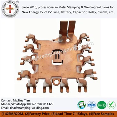
Power in Contacts Processing Technology: The production of mother ribs must strictly follow the process specifications to ensure that the processing quality meets the design requirements. The bending of the busbar requires controlling the minimum bending radius to avoid excessive bending that may cause mechanical damage and affect the mechanical strength and conductivity of the busbar; Tmgb overlap should ensure sufficient contact area, usually with an overlap length not less than 1.5 times the width of the busbar, to reduce contact resistance and ensure stable conductivity; The position and diameter of the mother row drilling hole need to be accurately positioned to avoid installation difficulties or stress concentration caused by drilling deviation; All cutting surfaces and drilling areas need to be deburred to prevent sharp edges from causing partial discharge and ensure safe operation.
Inverter Bus Bar Connection and Fixation: The reliability of busbar connection and fixation is directly related to the safe operation of low-voltage distribution systems, and the quality of each link needs to be strictly controlled. The clamping bolts of the busbar should be selected with high-strength specifications to ensure that the BusBar for Bussmann is installed firmly and flexibly, while also facilitating later maintenance and adjustment; Bolt tightening should be operated according to the specified torque value to ensure appropriate contact pressure, which not only avoids excessive contact resistance caused by insufficient pressure, but also prevents damage to the busbar caused by excessive pressure; Positive Bus Bar needs to be fixed with insulation supports to ensure that the distance between busbars and between busbars and other components meets regulatory requirements and avoid short-circuit hazards; The linear distance between the fixed supports of BusBar for Eaton should be determined based on the specifications and layout of the busbar, generally not exceeding 900mm, to ensure that the busbar does not undergo excessive deformation during operation.

New Technologies and Development Trends in Custom Bus Bars Design
With the continuous advancement of power engineering technology, the field of busbar design is also constantly innovating, with new technologies and concepts emerging, promoting the development of Bus Bar Connectors systems towards higher efficiency, reliability, and intelligence.
Modular design: Modular design has become an important trend in the development of AC BusBar systems. The Solid Copper Bus Bar system, which adopts a modular design, can achieve flexible configuration and efficient installation. The main busbar is usually arranged in the busbar room at the top of the switchgear. When the current is ≤ 4000A, a single-layer horizontal busbar is used, and when the current is>4000A, a double-layer horizontal busbar is used. By optimizing the ventilation design, the maximum current-carrying capacity of the horizontal busbar can be achieved at 7000A. The distribution busbar is often placed on the side of the cabinet. Each phase of the busbar below 3200A can be composed of a single or multiple copper bars, which are suitable for different current levels of application requirements and are easy to expand and maintain in the later stage.
Intelligent monitoring: The application of an intelligent PCB Bus Bars temperature monitoring system in the field of low-voltage distribution is gradually becoming popular. By integrating temperature sensors in key parts of the busbar, real-time monitoring of the temperature rise during busbar operation can be achieved. The temperature data collected by the sensors is uploaded to the monitoring system through wireless transmission, realizing real-time monitoring and data tracing of busbar temperature. When the temperature rise of the Cu Busbar exceeds the preset threshold, the system can automatically issue a warning or alarm signal to remind the operation and maintenance personnel to handle it in a timely manner, effectively preventing safety failures caused by overheating of the busbar and improving the intelligent operation and maintenance level of the low-voltage distribution system.

contact us
Our team focuses on producing busbar series and has a professional engineering team. If you are currently in the Low Voltage BusBar selection or technical evaluation stage, please provide project conditions and key parameters for engineering confirmation.