Copper Bus Bar Tapped: Characteristics, Processes and Welding Technology of Core Power Transmission Components
Dec 15, 2025
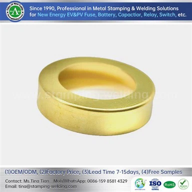
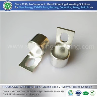
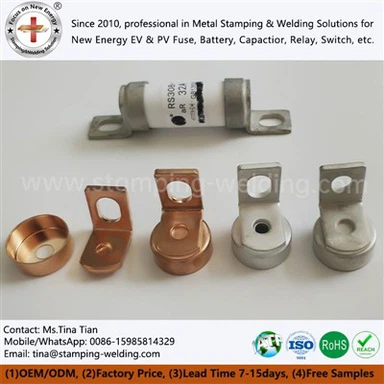
In the power system, Copper Bus Bar Tapped, as a key conductive transmission component, relies on its excellent electrical conductivity, thermal conductivity, corrosion resistance and mechanical strength to become the core choice for switchgear busbars, generator and transformer lead wires. Also known as copper busbar, it belongs to the category of rigid busbars. With the characteristic of no low-temperature brittleness, it is easy to weld and pressure process, which can easily adapt to the installation and operation needs of power equipment, and plays an irreplaceable role in power stations, industrial power distribution and other scenarios.
Specifications, Standards and Core Parameters
Implementation Standard: Strictly comply with the national standard GB/T5585.1-2005, divided into regular types with right angles and rounded corners, and special-shaped Grounding Copper Busbar customized according to drawings.
Dimension Range: The common cross-section is 30-3000mm², with thickness 3mm-12mm and width 10mm-125mm; in the wide specification range, the thickness covers 4~31.5mm and the width reaches 16~125mm.
Current-Carrying Calculation: At 40℃, the current-carrying capacity of a single piece ≈ B*(A+8.5) A (A is thickness, B is width, unit: mm), which is closely related to the working environment temperature.
Weight Calculation: The weight of a single 6-meter-long Power Distribution Bus Bar ≈ A*B*0.0534KG, and the weight per meter ≈ A*B*0.0089KG (unit: mm), making the calculation convenient and efficient.

Production Process and Selection Principles
Production Process
The production of Backplane Bus Bar needs to go through a complete closed loop: purchasing electrolytic copper → upward casting furnace process → continuous extrusion process → rolling head process → drawing process → straightening process → cutting process → inspection process → packaging process → delivery. Each process is strictly controlled to ensure quality.
Selection Principles
- Rectangular copper grounding bus bar: It has a large heat dissipation surface area. The cross-sectional area of a single strip does not exceed 1200mm², and 2~3 strips can be used in parallel for large current transmission.
- Channel-Shaped Grounding Bar Holes: Suitable for larger current transmission, with small skin effect, uniform current distribution and better heat dissipation conditions than multiple parallel rectangular copper bus bars. It should be selected according to the actual load size.

Welding Methods and Material Selection
Welding Methods
The connection of Copper ground Bus Bar in power stations includes bolt fastening method and welding method. Manual tungsten inert gas (TIG) welding is the preferred method to improve welding quality due to its concentrated heat and easy control of the molten pool, which is more suitable for the material characteristics of tin plated copper ground bar than gas welding.
Welding Materials
- Ground bus bar electrical panel Welding Wire: HS201 pure copper welding wire is selected, whose composition is similar to that of the base metal, ensuring the mechanical properties and corrosion resistance of the joint.
- Grounding Copper Busbar Flux: Matching gas welding flux CJ301. Before welding, mix it into a paste with absolute ethanol and brush it on the groove surface of the workpiece. Heat the welding wire to stick the flux before welding.

Key Welding Technical Points
Environmental Requirements: The Power Distribution Bus Bar ambient temperature of the welding site should be above 5℃, and argon should be used as the shielding gas.
Equipment and Parameters: The welding machine should have good performance and flexible current adjustment. DC positive polarity is adopted for manual TIG welding.
Preheating Treatment: Electric heating or flame heating is adopted. Backplane Bus Bar with thickness greater than 4mm requires multi-layer and multi-pass welding.
Welding Specifications: Avoid welding under constrained conditions, control the interlayer temperature, and adopt small swing amplitude and low heat input welding; the Grounding Bar Holes tack welding of the weld seam should be no less than 3 points, and the length of each point should be no less than 10mm.
Cleaning and Inspection: Timely clean welding black spots, and clean the interlayer with a stainless steel wire brush; copper grounding bus bar multiple inspections before welding, between layers and after welding, and continue only after confirming no defects.

Conclusion
As the core carrier of power transmission, the characteristics, specification selection, production process and welding technology of Copper ground Bus Bar directly affect the stable operation of the power system. Mastering the relevant professional knowledge of Copper Bus Bar Tapped is of great significance for industry practitioners to optimize equipment configuration, improve construction quality and ensure power safety. The performance advantages and technological upgrading will also continue to provide support for the high-quality development of the power industry.
contact us