Continuous Advancements in Powder-Coated Laminated Busbar Technology: Insulation Performance, Current-Carrying Capacity, And Precision Manufacturing Emerge As Key Industry Focus Areas
Oct 29, 2026
With the continuous development of new energy vehicles, energy storage systems, photovoltaic inverters, and industrial power electronics, high-current transmission systems now demand higher standards for the insulation reliability, space utilization, and long-term operational stability of connection components.
Laminated busbars-designed by combining multiple conductive layers with insulating materials-optimize current transmission paths and internal equipment layouts; they are increasingly utilized in battery systems, motor controllers, frequency converters, and uninterruptible power supplies (UPS). In this context, the powder-coating (dip-coating) insulation process creates a continuous protective layer on the surface of the conductive bars, providing both electrical insulation and surface protection for busbar assemblies with specific configurations.
Battery busbars are critical components in electrical interconnection systems for batteries. Their design must account for factors such as rated current, operating voltage, connection methods, heat dissipation, and available installation space. For energy storage battery packs and power systems in new energy vehicles, busbars must not only meet continuous current-carrying requirements but also withstand mechanical and electrical stresses resulting from vibrations, temperature fluctuations, and long-term operation. Through the careful design of conductor cross-sectional areas, connection hole positioning, and insulation structures, it is possible to enhance system integration efficiency and reduce the risk of abnormal temperature rises at connection points.
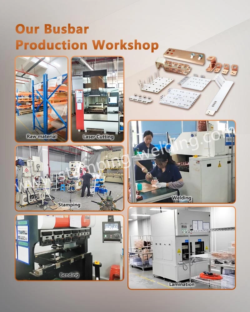
In terms of manufacturing, the production of powder-coated laminated busbars typically involves processing copper bars, deburring, surface pre-treatment, application of insulating powder, high-temperature curing, and final inspection. For products featuring multi-layer conductor structures, precise control over the spacing between layers, positioning accuracy, and overall dimensions is essential to ensure that all conductive layers are assembled according to design specifications. Compared to solutions that rely solely on insulating sleeves or film wrapping, the powder-coating process offers superior coverage; however, the actual insulation performance remains dependent on the condition of the substrate, the specific coating formulation, curing conditions, and the overall product architecture.
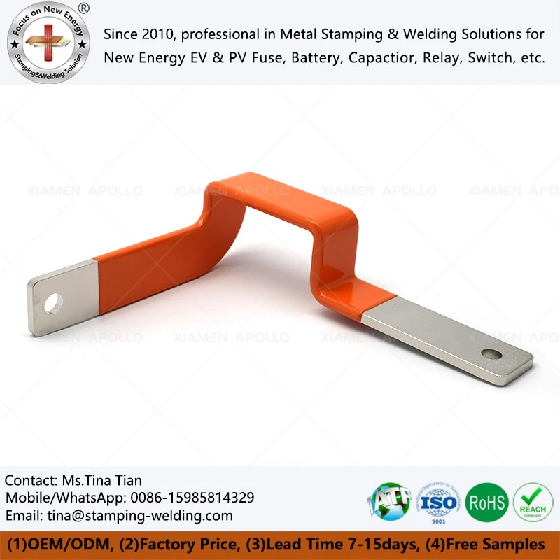
For applications requiring flexible connections or complex spatial layouts, PVC-dipped laminated flexible copper components combine insulating protection with a flexible conductor structure, effectively meeting the installation and connectivity needs of specific equipment.
The design of such products requires careful evaluation of the bending radius, conductor cross-sectional area, the configuration of connection terminals, and the integrity of the insulation layer following repeated bending. For applications requiring accommodation of assembly tolerances or vibrational displacement, the mechanical durability of flexible structures must be verified against actual operating conditions to prevent conductor fatigue or damage to the insulation layer caused by improper bending.
The uniformity and adhesion of the insulation layer are critical quality control metrics for powder-coated busbars. Inadequate surface pretreatment, uneven coating application, or mismatched curing parameters can lead to localized weak points, air bubbles, cracking, or poor adhesion. Consequently, the manufacturing process must strictly control conductor surface cleanliness, edge conditions, powder coverage, and curing parameters. Furthermore, the insulation performance must be validated based on the product's rated operating voltage and intended service environment.
For battery interconnection solutions that require both high electrical conductivity and surface protection, a design combining a copper conductor, a tin-plated surface, and an external insulation layer-such as a tin-coated insulated flat copper busbar-may be employed.
The tin-plated layer enhances the oxidation resistance of the copper surface and is suitable for electrical contact interfaces that meet specific design requirements. However, the plating thickness, the condition of the base material, and the design of the contact interface must be determined based on actual service conditions; the overall electrical performance cannot be judged solely by the surface treatment method.
Operating environments differ between power battery systems for new energy vehicles (NEVs) and energy storage systems (ESS). NEV applications typically necessitate consideration of vehicle vibration, spatial constraints, temperature cycling, and transient loads, whereas ESS applications require a focus on long-term current-carrying capacity, heat dissipation, insulation reliability, and maintenance requirements. Therefore, the design of busbar products should not be limited to conductor materials and physical dimensions; it must also comprehensively account for insulation ratings, installation methods, connection reliability, and the thermal management of the overall system.
In the context of NEV battery interconnections, PVC-dipped, nickel-plated copper busbars represent a structural solution that combines nickel-plated conductors with an insulating coating. While nickel plating can provide necessary surface protection and meet specific connection requirements, its suitability must be verified by considering the conductor material, the mating contact surfaces, operating temperatures, and electrical performance specifications. In cases involving the connection of dissimilar metals-such as copper and aluminum-particular attention must be paid to the risk of electrochemical corrosion at the interface, and appropriate transition connection structures should be incorporated into the design.
As power electronic equipment trends toward higher power density and greater compactness, the structural design of insulated busbars increasingly emphasizes electrical clearance, creepage distance, the integrity of edge insulation, and installation precision. The insulation design for a busbar must be evaluated based on factors such as operating voltage, pollution degree, altitude, and applicable standards; coating thickness alone is not a sufficient metric for assessing insulation reliability. In areas featuring sharp corners, cutouts, or connection holes, the insulation coverage must be carefully inspected to prevent localized electric field concentration or defects arising from the manufacturing process that could compromise long-term performance.
For energy storage battery modules and packs, PVC-dipped insulated busbar connectors can be customized to suit specific battery arrangements and electrical connection paths. These connectors must align with the spatial positioning of battery terminals, the required conductor cross-sectional area, and installation tolerances, while also accounting for the operational space needed for assembly tools. In mass-production projects, verifying the dimensional fit between the connectors and battery modules in advance helps minimize on-site rework and ensures greater consistency during the assembly process.
The electrical conductivity of a busbar depends not only on the material itself but also on its connection structure and manufacturing precision. While pure copper offers high conductivity and is suitable for a wide range of power connection applications, the thickness, width, bending geometry, and design of connection holes all influence actual temperature rise and mechanical performance. When using pure copper insulated busbars, the cross-sectional area must be determined based on the rated current and operating environment, with current-carrying capacity verified through appropriate temperature-rise testing. Furthermore, the insulation material must be compatible with the expected operating temperatures and environmental conditions to ensure the equipment's long-term reliability.
In custom manufacturing, the precision of conductor processing is equally critical. Techniques such as laser cutting, stamping, bending, and machining can affect edge quality, the dimensions of holes, and overall assembly accuracy. Burrs or sharp edges left after cutting can damage the insulation coating and lead to localized electric field concentration. Consequently, the production workflow should incorporate necessary deburring, chamfering, and surface inspection steps, alongside in-process checks for critical dimensions.
For connection products that combine metal conductors with insulating sleeves-such as custom solid power busbars with insulated dipping-process coatings-the structural design can be tailored to specific equipment space constraints and protection requirements. In such cases, it is essential to verify the temperature resistance, attachment method, and coverage area of the insulating sleeve, while also ensuring that any exposed (uninsulated) sections at the connection terminals comply with electrical safety standards. Since different insulation processes offer varying performance characteristics, engineering selection should be based on actual product test results and relevant application standards.
Quality verification typically includes dielectric withstand (hipot) testing, insulation resistance testing, dimensional inspection, and temperature-rise testing; the specific tests required depend on the product's intended use and applicable standards. For applications involving thermal cycling or mechanical vibration, additional environmental and durability testing should be conducted to check for cracks, delamination, or other anomalies in the insulation layer. Establishing clear inspection criteria and batch traceability mechanisms is key to ensuring consistent quality across mass-produced units.
In applications with limited internal space, insulated flat copper busbars can optimize connection layouts; their design-including bending angles, hole positioning, and insulation coverage-can be customized to meet specific installation requirements. During the design phase, it is critical to evaluate conductor spacing, heat dissipation paths, and the temperature rating of the insulation material to prevent issues such as poor heat dissipation or compromised electrical safety resulting from an overly compact structure.
As the demand for custom busbars grows, the combinations of insulation processes, conductor materials, and surface treatments have become increasingly diverse. PVC-insulated copper busbars are suitable for electrical connections that align with their specific material properties and operating conditions; selection should account for the insulation's temperature resistance, wear resistance, chemical resistance, and electrical performance. If the operating environment involves high temperatures, oil exposure, or specific chemical agents, the appropriate insulation material must be selected for those particular conditions-one should not assume that all PVC coatings are suitable for every environment.
Industry trends indicate that powder-coated (dipped) busbars are evolving toward greater precision in machining, more stable insulation processes, and modular assembly. By optimizing process parameters, enhancing in-line inspection, and strengthening sample validation, manufacturers can achieve better control over coating quality, dimensional tolerances, and batch-to-batch consistency. For manufacturers of new energy vehicles, energy storage systems, and industrial power electronics, the engineering collaboration capabilities of a busbar supplier are crucial-especially during the product development phase, when technical drawings, material specifications, insulation requirements, and validation standards must be confirmed in a timely manner.
During the engineering procurement process, it is advisable for the procurement and R&D teams to provide-at an early stage-details such as busbar drawings, rated current, operating voltage, installation space, conductor material, surface treatment, and insulation requirements. Additionally, requirements for sample validation, batch delivery, and inspection documentation should be clearly defined.
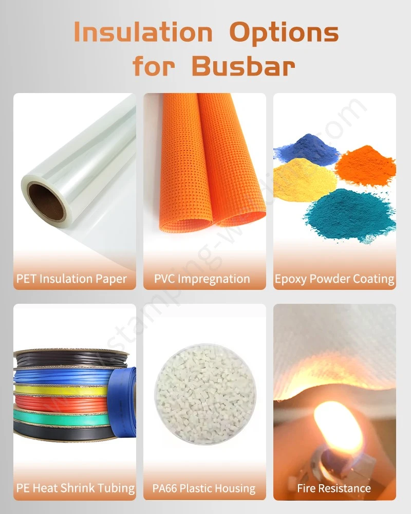
For customized PVC-insulated copper busbars, further clarification is needed regarding the operating environment, connection terminal types, dimensional tolerances, and expected service conditions; this enables the supplier to assess manufacturing feasibility and develop an appropriate production plan.
Through early-stage technical communication and sample testing, engineering teams can more accurately determine whether a busbar design meets equipment requirements, thereby reducing the risk of assembly modifications or quality issues later on. If you have requirements for customized powder-coated busbars, laminated busbars, or other types of insulated copper busbars, please share your product drawings, technical specifications, and application details. We look forward to discussing material selection, manufacturing processes, sample production, and arrangements for mass production.
contact us