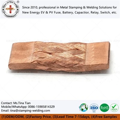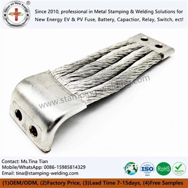
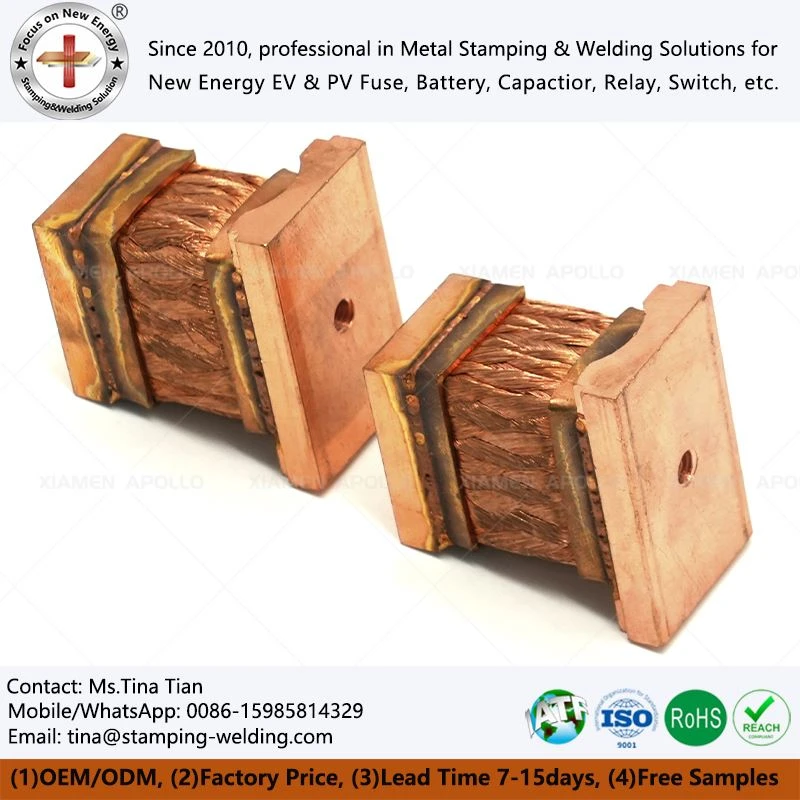

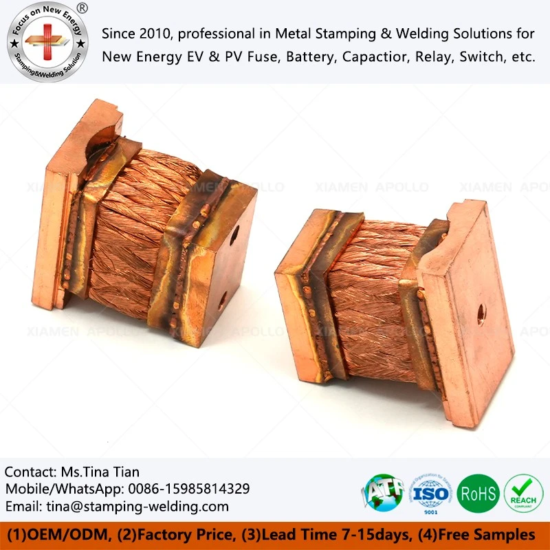
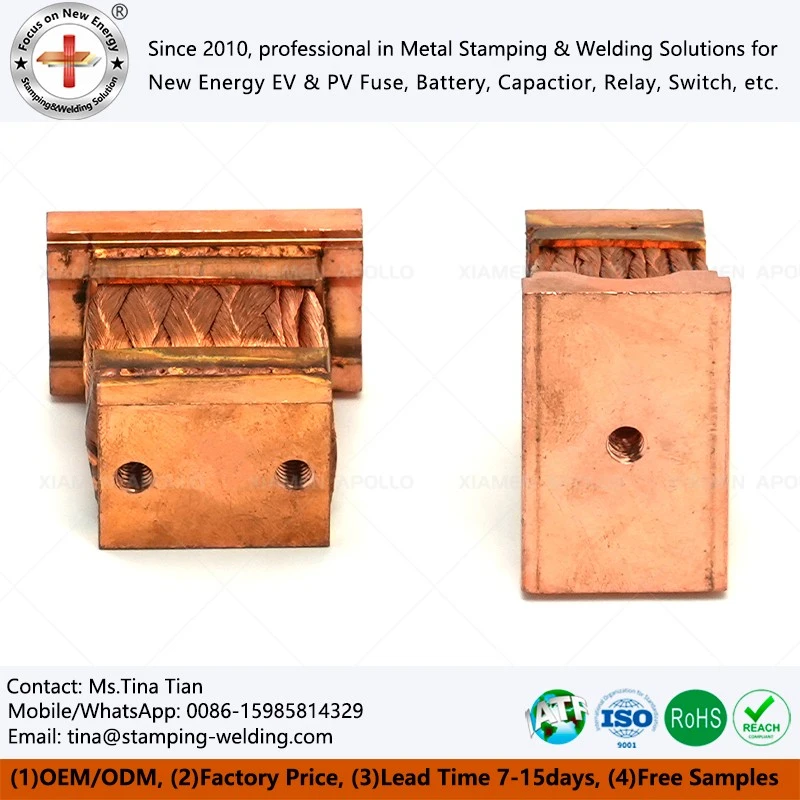
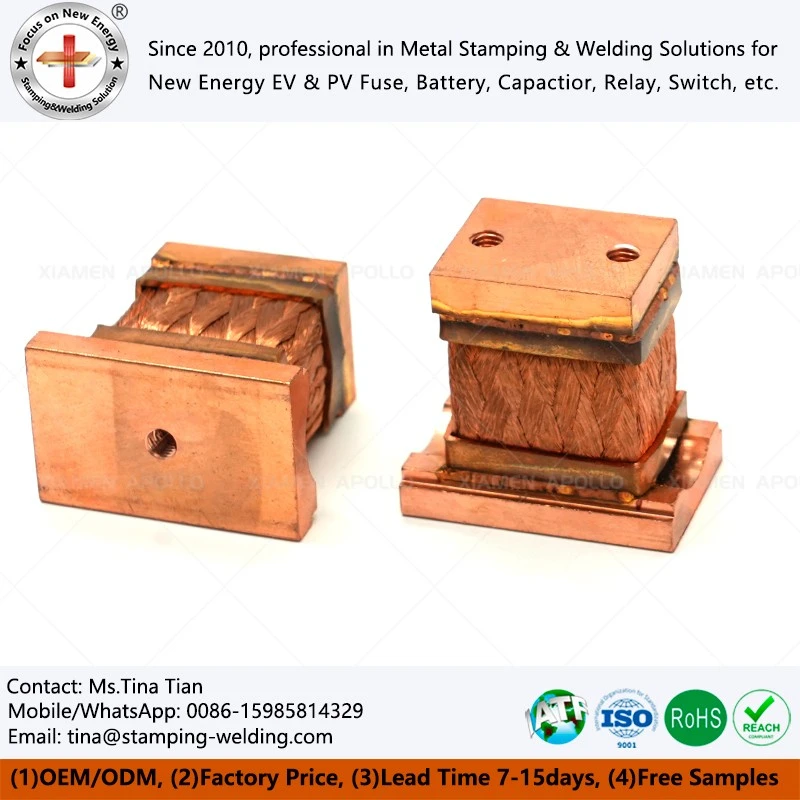
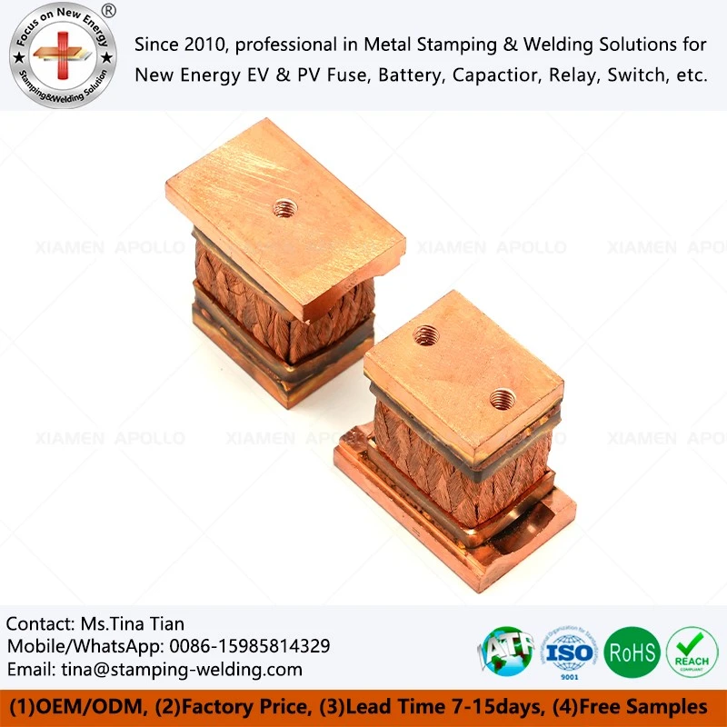
Braided Flexible Power Shunts
Unlike standard grounding braids, braided flexible power shunts are specifically designed to carry operating current—or current under particular service conditions—rather than merely serving as a protective ground connection. These components require careful consideration of factors such as conductor cross-sectional area, connection resistance, contact interface conditions, operating temperature rise, and mechanical motion, all to ensure stable current transmission across the flexible connection zone. In high-current electrical systems, components such as busbars, switch contacts, transformer terminals, circuit breaker connection points, and conductive elements within battery systems may experience relative motion due to assembly tolerances, equipment vibration, thermal expansion, or structural displacement. If a completely rigid conductive connection were used, mechanical stress could become concentrated at the connection points.
- Fast Delievery
- Quality Assurance
- 24/7 Customer Service
Product Introduction
Flexible electrical shunts are constructed primarily from multi-strand copper braids, which are cut to specific lengths, processed for precise end-face finishing, and fitted with terminal connections. In essence, they serve as low-resistance, flexible conductors for current shunting or sampling. They fulfill three distinct roles:
Shunt: Distributes current within parallel circuits to ensure balanced loads across various branches.
Sampler: Generates a small, precise voltage drop-proportional to the current-due to its stable, low-value resistance, which can be read by ammeters, protection systems, or metering devices.
Flexible Connector: Accommodates assembly misalignments, thermal expansion/contraction, and mechanical vibrations, ensuring long-term connection reliability.
Compared to rigid shunts, their primary advantage lies in the installation flexibility provided by their "flexible" nature; factors such as height discrepancies between busbars, space constraints within enclosures, or operational displacement of equipment no longer pose rigid obstacles.
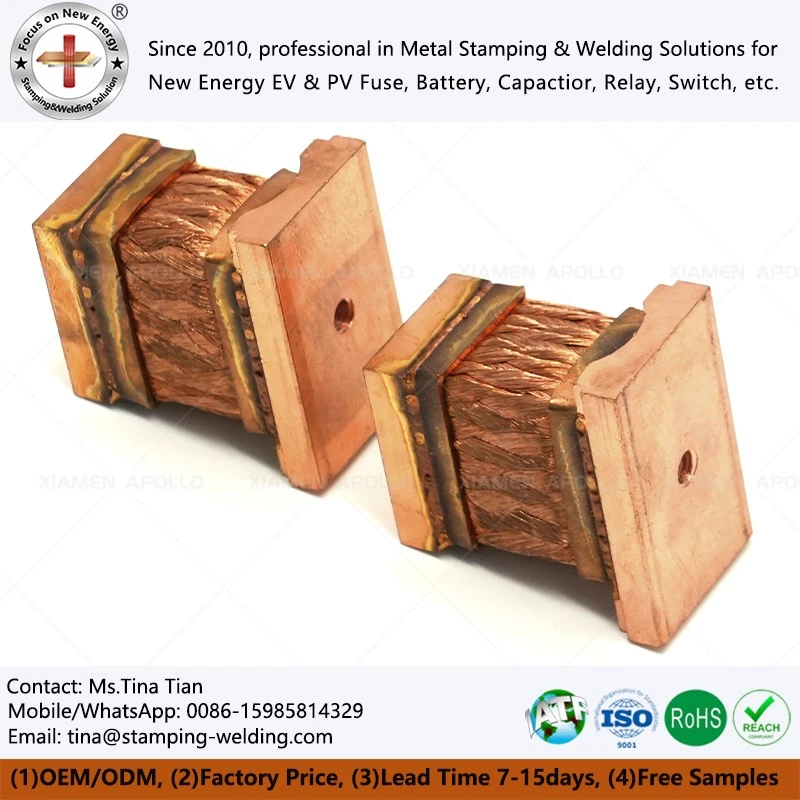
Technical Features for Braided Wire Flexible Copper
Controlled Resistance Performance
Parameters-including wire diameter, braid density, number of layers, and welding heat input-are strictly maintained according to design specifications. This ensures consistent resistance values across a single production batch, minimizing performance variations after installation.
01
Optimized Temperature Rise and Current Distribution
Tight interlayer contact within the compressed (laminated) sections ensures a more uniform distribution of current across the thickness, helping to prevent the formation of localized hot spots.
02
Stable Contact Resistance
Precise control over the flatness of terminal mating surfaces and thickness tolerances ensures consistent contact conditions upon bolting, reducing the risk of resistance drift during long-term operation.
03
Balanced Flexibility and Structural Integrity
The braided sections retain the ability to bend and expand, while the compressed sections provide sufficient rigidity to prevent the wire strands from splaying or undergoing localized crushing during fastening.
04
Integrated Sensing/Sampling Design
The terminal layout allows for the separation of current-carrying and potential-sensing (voltage-sampling) points, minimizing the impact of contact conditions at the mating interface on measurement accuracy.
05
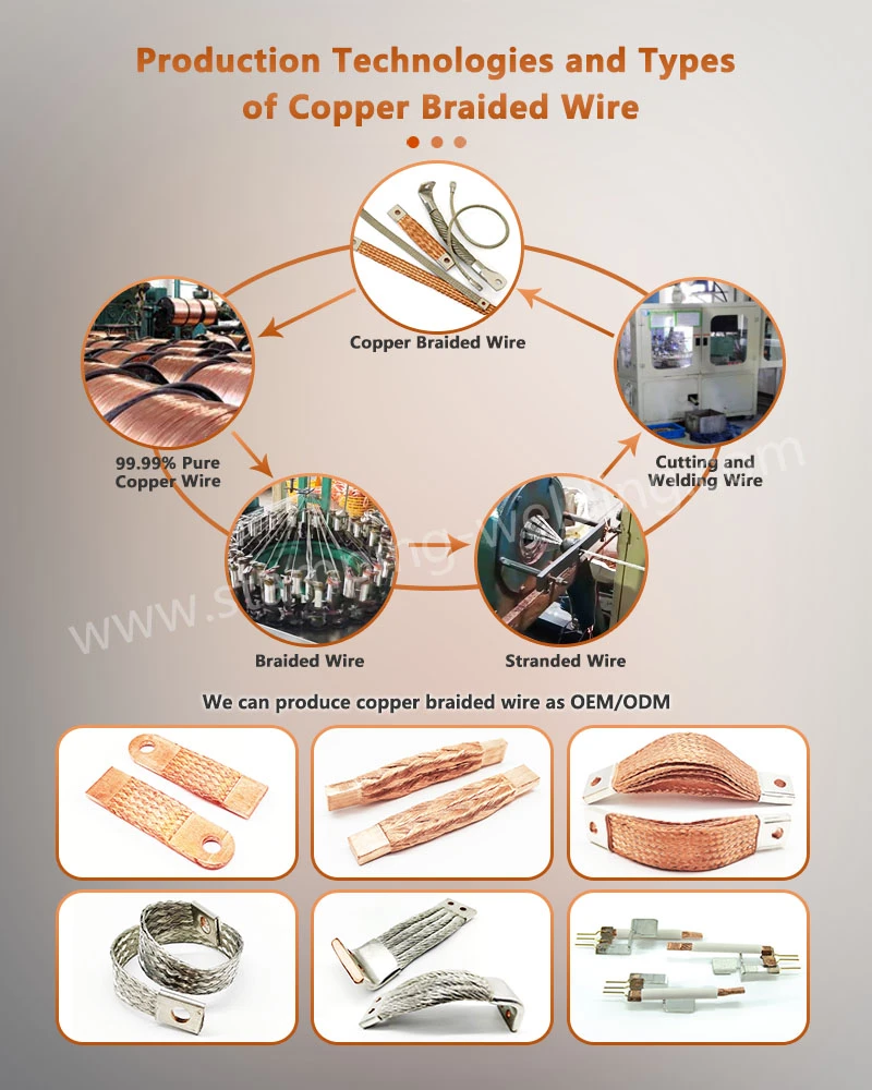
Application Advantages for Braided Copper Flexible Wire Connectors
New Energy and Energy Storage Systems (ESS)
Flexible interconnections between battery clusters, PCS inverters, and container busbar systems, designed to accommodate thermal management requirements under complex operating conditions.
High-Voltage Power Transmission, Distribution, and Transformer Engineering
Dynamic interconnections between transformer secondary-side bushings and high-voltage switchgear, as well as within Gas-Insulated Switchgear (GIS) installations.
Electrolysis and Electroplating Industries
Capable of withstanding exposure to strong acid/alkali vapors and high-humidity environments, providing stable, low-loss power paths for high-current rectifiers and electrolytic cells.
Rail Transit and Marine Vessels
Ensures long-term, reliable power transmission for locomotive traction motors and marine diesel generator sets, even under conditions of intense oscillation and frequent vibration.
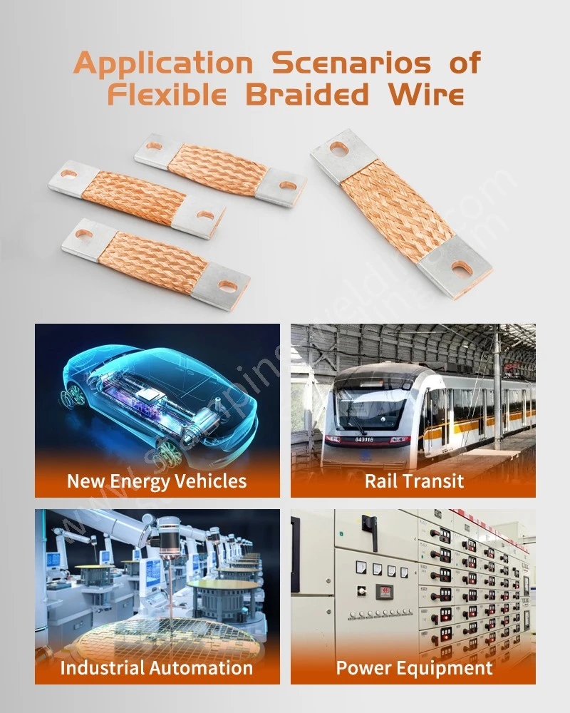
Frequently Asked Questions for CU Flex Busbar
Q1: How do Flexible Copper Braided Connector Bus Bars differ from standard copper braided flexible connectors?
-
A: While standard flexible connectors are designed for general-purpose flexible electrical conduction, power shunts are engineered with a focus on low-impedance paths and suitability for specific industrial power operating conditions-featuring optimized braid density, specialized end-termination, and cross-sectional design. They are ideal for use as flexible segments in main circuits or for dedicated shunting/bridging applications.
Q2: Can these products be customized to fit the specific installation space within switchgear or transformers?
-
A: Yes. We offer customization based on current ratings, available space, bending requirements, and connection methods. This includes adjusting the number of braided layers, width, length, and terminal configurations, with full engineering support provided throughout the process.
Q3: How is long-term reliability ensured in environments subject to continuous vibration?
-
A: The flexible braided structure is inherently designed to absorb vibration and displacement. When combined with robust end-termination (crimping or welding) and appropriate surface treatments, the risk of mechanical fatigue and contact degradation is minimized. Specific solutions are evaluated based on the actual vibration conditions.
Q4: How should the appropriate surface treatment be selected?
-
A: For standard, dry indoor environments, tin plating is typically used to enhance solderability and oxidation resistance. In humid or mildly corrosive environments, nickel plating or other protective coatings may be considered. The choice depends on the specific operating conditions and assembly processes.
Q5: What is the typical workflow, from initial technical consultation to volume delivery?
-
A: The process generally begins with defining the technical solution based on the client's requirements-such as current, space, environmental conditions, and interface specifications-followed by sample validation and process finalization. Our approach prioritizes engineering alignment and process control, rather than competing solely on price.
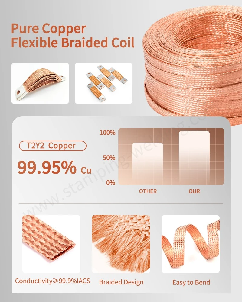
contact us
We specialize in the engineering, matching, and volume delivery of braided flexible power shunts. Our comprehensive capabilities span from the design of braided structures and terminal processing to operational condition assessment. We provide tailored solutions based on your specific requirements for current, space, and environmental conditions. Please submit your application parameters, and our technical team will assist you with component selection and verification.
Hot Tags: Braided Flexible Power Shunts, Flexible Copper Shunt, Braided Copper Shunt, Copper Braid Power Connector, Flexible Current Shunt