Busbar Interconnect Design for 48V/51.2V Home Energy Storage Systems (HESS): Plug-in Terminals & Current Density
Oct 21, 2026
For 5–15 kWh home energy storage systems (HESS), a 48V or 51.2V battery interconnect must carry high current within a compact enclosure while maintaining controlled temperature rise, stable contact resistance, and safe insulation. At 100–200 A, busbar cross-section alone does not determine performance: terminal constriction, plug-in contact force, joint resistance, airflow and adjacent heat sources can dominate local heating. A reliable design therefore combines electrical sizing, stamped spring-contact geometry, thermal validation, and an insulation system rated for the actual operating environment.
48V/51.2V HESS Busbar Sizing: 100–200A Current and Thermal Limits
Power and current in a 5–15 kWh home battery
Nominal battery voltage and energy capacity describe different system characteristics. A 51.2V, 100Ah battery stores approximately 5.12 kWh at nominal voltage; a 51.2V, 300Ah battery stores approximately 15.36 kWh. Actual usable energy depends on the battery management system (BMS), operating limits, and system configuration.
At 51.2V, a 5 kW DC load draws approximately 97.7 A before accounting for voltage variation and transient demand. A 10 kW DC load draws approximately 195.3 A. These estimates explain why some low-voltage HESS designs require 100–200 A interconnects even when the battery's energy capacity is relatively modest.
The final current rating must account for continuous and peak loads, duty cycle, ambient temperature, enclosure airflow, installation orientation, and allowable component temperature. An inverter's short-duration peak rating should not be treated as a continuous busbar current rating.
The following values illustrate the relationship between current, cross-section, and nominal current density. They are calculation examples, not universal design limits.
| Current | Copper cross-section | Example geometry | Nominal current density |
| 100 A | 20 mm² | 20 mm × 1 mm | 5 A/mm² |
| 100 A | 30 mm² | 30 mm × 1 mm | 3.33 A/mm² |
| 150 A | 30 mm² | 30 mm × 1 mm | 5 A/mm² |
| 200 A | 40 mm² | 40 mm × 1 mm | 5 A/mm² |
| 200 A | 60 mm² | 30 mm × 2 mm | 3.33 A/mm² |
Two busbars with the same nominal current density can produce different temperature rises because their lengths, surface areas, mounting points and thermal environments differ. Current density is useful for preliminary sizing, but it cannot replace thermal analysis and testing.
At 200 A, a joint resistance of 100 µΩ generates 4 W of heat. If the resistance increases to 250 µΩ, the same current generates 10 W. This localized heating can be more consequential than the average temperature of the main copper section.
For HESS busbar design, evaluate the complete current path: copper body, plug-in contact, bolted interface, welded joint, and connection to the battery or inverter terminal. Each interface can contribute additional resistance.
Stamped Plug-in Busbar Terminals: Contact Force, Retention and Wear
Spring-contact geometry for repeated mating cycles
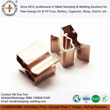
Plug-in terminals reduce assembly time by allowing battery modules to connect through guided mating interfaces. Their performance depends on spring geometry, material temper, plating, insertion alignment, and the number of mating cycles.
Stamped spring contacts can be designed with cantilever beams, dual-beam contacts, or other compliant geometries. The correct structure depends on current demand, available space, contact travel, and required retention force. Increasing spring force may improve contact stability, but it can also increase insertion force, contact wear, and mechanical stress.
Key design controls include:
Contact normal force: Maintain sufficient force over the specified tolerance range without exceeding the elastic limit of the spring material.
Beam geometry: Control beam length, width, thickness, and formed angle. Small thickness variations can significantly affect spring stiffness.
Mating alignment: Use lead-in features and mechanical guides to prevent edge loading, incomplete engagement, and contact deformation.
Retention: Design a positive latch or mechanical stop where required; do not rely on friction alone if the assembly must resist defined vibration loads.
Contact plating: Select a plating system compatible with the base metal, mating material, expected wear, and environmental exposure.
Thermal stability: Verify that contact force and electrical resistance remain within specification after current cycling and temperature exposure.
A plug-in connection should not be approved solely because it can carry the target current in a single initial test. Repeated mating, vibration, and thermal cycling can change contact resistance over the service life.
C1100 copper versus spring copper alloys for stamped contacts
C1100 copper offers high conductivity, but pure copper is generally less suitable for a spring element that must retain substantial elastic force through repeated deflection. Spring-capable copper alloys may provide a better balance of strength, fatigue performance and conductivity.
| Material category | Electrical behavior | Mechanical behavior | Typical design consideration |
| C1100 / high-conductivity copper | High conductivity | Relatively soft in many tempers | Suitable for busbar bodies and conductive plates; spring features may require reinforcement |
| Phosphor bronze | Lower conductivity than pure copper | Useful spring properties in suitable tempers | Consider where spring retention and fatigue resistance outweigh the conductivity reduction |
| Copper-nickel-silicon alloys | Conductivity varies by grade and temper | Can provide high strength and stress-relaxation resistance | Evaluate for compact, highly loaded spring contacts |
| C2680 brass | Moderate conductivity relative to pure copper | Good formability and useful strength in suitable tempers | Suitable for selected terminal and stamped components; verify contact heating and spring requirements |
The selected grade, temper, and grain direction must be compatible with the stamping and forming sequence. Material substitution requires revalidation of spring force, fatigue behavior, contact resistance and temperature rise.
Contact resistance and insertion-force validation
Contact resistance is affected by real contact area, surface films, plating condition, contact force, and mechanical wear. The apparent geometric contact area is not equal to the microscopic area carrying current. A connection with insufficient force can develop localized current constriction and heating.
A production validation plan should measure:
| Parameter | Test approach | Acceptance basis |
| Initial contact resistance | Four-wire Kelvin measurement | Drawing or customer-defined maximum |
| Insertion and extraction force | Force-displacement test over specified travel | Defined minimum and maximum force |
| Contact retention | Axial pull or specified retention test | Application-specific mechanical requirement |
| Mating durability | Repeated mating and unmating cycles | Resistance and force limits after the specified cycle count |
| Spring-force retention | Measure force before and after thermal exposure | Maximum permissible force loss |
| Electrical temperature rise | Apply the specified current waveform in the representative assembly | Component and system temperature limits |
Measurement fixtures should reproduce the intended mating depth and contact points. Otherwise, test results may include fixture variability or fail to represent the installed connection.
Request Free DFM Evaluation & Quote
Thermal Simulation for 100–200A HESS Copper Interconnects
Heat generation in compact battery enclosures
In a compact 5–15 kWh HESS enclosure, thermal performance depends on more than copper cross-section. Battery spacing, enclosure walls, inverter heat sources, terminal orientation, and natural or forced convection influence the temperature distribution. A busbar that performs adequately in open-air testing may run hotter after installation inside a sealed battery cabinet.
Thermal analysis should begin with a defined operating envelope:
Continuous current and peak-current magnitude, duration, and repetition rate.
Minimum and maximum ambient temperatures specified for the installation.
Copper grade, thickness, geometry and temperature-dependent electrical resistivity.
Contact and joint resistance, including the plug-in terminal interface.
Enclosure geometry, neighboring components, and available airflow.
Maximum allowable temperatures for the conductor, plating, insulation, and adjacent polymer parts.
The simulation should identify local hot spots at contact interfaces, narrow conductive necks, mounting transitions, and current-sharing junctions. Where parallel current paths are used, unequal contact resistance or geometric asymmetry can cause uneven current distribution.
Thermal simulation versus physical temperature-rise testing
Finite element analysis (FEA) or computational fluid dynamics (CFD) can estimate temperature distribution and help compare design variants. The results depend on boundary conditions, material properties, contact-resistance inputs and the accuracy of the enclosure model.
| Method | Primary purpose | Limitation |
| Electrical-thermal FEA | Maps resistive heat generation and conductor temperature | Depends on realistic electrical and thermal material data |
| CFD | Evaluates airflow, convection, and heat transfer within the enclosure | Sensitive to fan curves, vent restrictions and boundary conditions |
| Infrared thermography | Identifies surface hot spots during a controlled current test | Emissivity and viewing access can affect readings |
| Thermocouple measurement | Records temperature at defined contact and conductor locations | Sensor placement can disturb small interfaces or miss localized peaks |
| Four-wire resistance measurement | Tracks electrical resistance before and after thermal exposure | Does not independently identify the physical location of a hot spot |
Simulation should guide prototype testing, not replace it. The validation report should document the applied current, test duration, ambient conditions, sensor positions, stabilization criterion, and measured maximum temperature. If the system operates under cyclic loads, the test should reproduce a representative duty cycle rather than relying only on a single steady-state point.
Design actions for reducing temperature rise
| Design variable | Potential thermal benefit | Engineering trade-off |
| Increased copper cross-section | Reduces bulk conductor resistance | Requires more enclosure space and material |
| Shorter current path | Reduces conductor resistance | May constrain battery-module arrangement |
| Wider or thicker contact region | Can reduce current constriction | May increase insertion force or alter spring compliance |
| Improved contact-force consistency | Helps stabilize interface resistance | Requires control of spring geometry, temper, and assembly tolerance |
| Reduced joint resistance | Lowers localized I2R heating | Requires validated joining and contact-surface processes |
| Improved airflow or heat spreading | Can lower component temperature | May affect enclosure sealing, noise, or packaging |
A design review should compare the temperature rise of the busbar body and each critical connection separately. If the main conductor remains cool while the plug-in interface overheats, increasing the entire busbar cross-section may add cost and bulk without correcting the primary failure mechanism.
HESS Electrical Insulation: UL 94 V-0, Heat-Shrink Tubing and Touch Protection
Selecting molded terminal housings and insulation systems
Low-voltage nominal operation does not eliminate electrical hazards. A 48V or 51.2V battery can supply high fault current, and a conductive tool or loose metal part can bridge exposed terminals. Insulation design must therefore address accidental contact, short-circuit risk, assembly errors, and the system's maximum operating voltage.
Molded insulating housings can guide plug-in terminals, prevent unintended contact, and provide mechanical keying. Heat-shrink tubing can insulate selected exposed conductor sections, while epoxy powder coating may be appropriate for other busbar applications. These methods serve different functions and should not be treated as interchangeable.
UL 94 V-0 is a material flammability classification under specified vertical-burning test conditions. It does not, by itself, establish dielectric strength, long-term thermal endurance, resistance to tracking, or the safety of a finished enclosure. The resin grade and exact material classification must be verified against the supplier's documentation.
Molded insulation versus heat-shrink tubing versus epoxy powder coating
| Insulation method | Typical application | Advantages | Design limitations |
| Molded polymer housing | Plug-in terminals, shrouds and keyed interfaces | Integrates touch protection, alignment and retention features | Requires mold tooling; dimensional shrinkage and tolerance stack-up affect fit |
| Heat-shrink tubing | Exposed busbar sections and selected joints | Can be applied after forming or joining; useful for localized insulation | Coverage at edges and junctions requires control; may not provide mechanical guidance or retention |
| Epoxy powder coating | Busbars and metal components requiring a bonded insulating layer | Can provide durable coverage over suitable geometries | Coating thickness and edge coverage vary with geometry; masking is required at conductive interfaces |
| Insulating barriers or covers | Separation between adjacent conductors and service-access areas | Provides physical separation and can reduce accidental contact risk | Must remain securely positioned under vibration and servicing |
The insulation architecture should be selected according to assembly sequence, maintenance access, conductor geometry and electrical safety requirements. Combining a molded shroud with localized heat-shrink insulation may be appropriate where a single method cannot protect all exposed conductive regions.
Creepage, clearance and dielectric verification
Clearance is the shortest distance through air between conductive parts; creepage is the shortest distance along an insulating surface.
Required distances depend on factors such as working voltage, transient overvoltage, pollution conditions, insulation material, and the applicable product standard. There is no single universal clearance value suitable for every HESS design.
The insulation design review should include:
Working voltage: Consider the maximum operating voltage, not only the nominal 48V or 51.2V label.
Transient conditions: Evaluate switching events and system-level voltage disturbances where applicable.
Material properties: Verify dielectric strength, tracking performance, and temperature rating from the exact resin or insulation specification.
Mechanical protection: Prevent sharp stamped edges from cutting tubing or damaging molded insulation during assembly.
Tolerance stack-up: Confirm minimum clearance and creepage after accounting for busbar position, housing shrinkage, and assembly variation.
Fault conditions: Evaluate the consequences of insulation damage, loose hardware and conductive debris.
Dielectric withstand testing, insulation-resistance testing and inspection of finished assemblies should use the applicable product specification and test method. A material's reported dielectric breakdown strength, expressed in kV/mm, cannot be used alone to establish the withstand voltage of a finished assembly with seams, edges, air gaps and local stress concentrations.
UL 94 V-0 and insulation process quality controls
For molded terminal housings, process controls should cover resin identification, drying where required, molding temperature, fill consistency, dimensional stability and visual defects. For heat-shrink tubing, control the material grade, recovered dimensions, application temperature, and coverage. For epoxy powder coating, control pretreatment, coating thickness, cure conditions, and masking.
| Quality checkpoint | Failure mode addressed | Verification method |
| Resin grade and flame rating | Incorrect polymer or unverified UL 94 classification | Supplier documentation and material traceability |
| Molded housing dimensions | Loose fit, terminal misalignment, or insufficient protection | Dimensional inspection and assembly-fit checks |
| Heat-shrink recovery | Exposed metal, gaps, or poor fit | Visual inspection and dimensional checks |
| Coating thickness | Insufficient insulation or interference with assembly | Thickness measurement at defined locations |
| Coating adhesion and cure | Peeling, cracking, or damage during handling | Applicable adhesion test and cure-process verification |
| Minimum clearance and creepage | Electrical separation below design requirements | Drawing-based inspection and assembly verification |
| Post-assembly integrity | Insulation damage caused by sharp edges or insertion | Visual inspection and specified electrical testing |
Request Free DFM Evaluation & Quote
Modular Copper Busbar Kits for 5–15 kWh Home Energy Storage Systems
Designing the complete battery interconnect kit
A modular HESS busbar kit should be engineered around the battery module layout, BMS architecture, inverter connection, and enclosure constraints. Designing each copper link independently can introduce alignment problems, inconsistent current paths, and additional assembly steps.
A coordinated kit may include positive and negative busbars, module-to-module interconnects, stamped plug-in terminals, insulating housings, protective covers, and defined mounting hardware. The exact scope depends on the battery configuration and the customer's assembly method.
Key design considerations include:
Polarity control: Use geometry, labels, or mechanical keying to reduce the risk of reverse connection during assembly.
Assembly sequence: Ensure the busbar can be installed without forcing the terminal or damaging the insulation.
Service access: Allow the specified maintenance procedure without exposing adjacent live conductors unnecessarily.
Current-path symmetry: Where parallel branches are used, evaluate path resistance and connection geometry to support balanced current sharing.
Manufacturing tolerance: Review the cumulative variation of stamped parts, molded housings, module positions, and mounting features.
Traceability: Define part identification, material records, and inspection checkpoints appropriate to the production program.
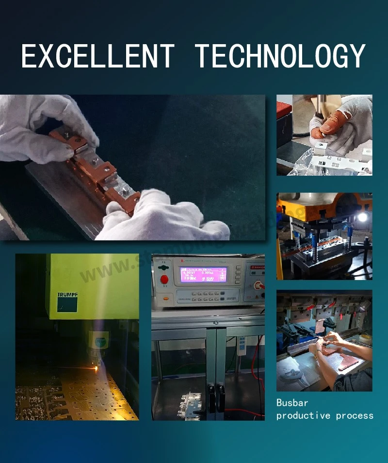
Manufacturing and inspection workflow for OEM copper interconnects
| Manufacturing stage | Typical controls | Required evidence, as specified |
| Engineering review | Current requirement, material selection, interface dimensions and insulation layout | Approved drawing and design-review records |
| Copper blanking and stamping | Die clearance, burr direction, flatness and hole position | Dimensional inspection and tool-control records |
| Terminal forming | Spring geometry, formed angle and contact alignment | Critical-dimension results and force testing where applicable |
| Joining | Joint position, heat input and fusion quality where welding is specified | Process records and joint inspection |
| Surface finishing | Plating or coating coverage and thickness | Coating measurements and material certificates |
| Insulation assembly | Housing fit, tubing coverage and protection of contact zones | Assembly inspection and applicable electrical tests |
| Final validation | Resistance, temperature rise, and mechanical integrity | Test report against the agreed product specification |
CMM inspection can be used for complex three-dimensional features and datum relationships where the measurement task justifies it. For high-volume stamping, dedicated gauges and automated optical inspection may provide faster production feedback for selected critical dimensions. The inspection method should match the tolerance, feature geometry, and required measurement uncertainty.
Data required for a Home Energy Storage Busbar quotation
To evaluate a new Home Energy Storage Busbar design, the engineering team should provide the following information wherever available:
2D drawings and 3D CAD files, including module interfaces and enclosure constraints.
Nominal battery voltage, maximum operating voltage, and continuous and peak current profiles.
Copper grade, temper, thickness, plating requirements, and allowable resistance.
Maximum permitted temperature rise and the intended thermal environment.
Plug-in terminal insertion force, extraction force, retention requirement, and mating-cycle target.
Insulation material, flame classification, clearance and creepage requirements.
Prototype quantity, forecast annual volume, assembly method, and requested quality documentation.
For a 48V Battery Pack Busbar Manufacturer or HESS Copper Interconnect Supplier evaluation, the relevant comparison is not copper price alone. It includes contact resistance, dimensional repeatability, assembly time, insulation integrity, validation scope, and the ability to maintain consistent production output.
FAQ: HESS Copper Busbar Sizing, Plug-in Contacts and Insulation
How much copper cross-section is required for a 200A, 51.2V home energy storage busbar?
There is no universal cross-section for 200A operation. Preliminary sizing uses conductor resistance and current density, followed by thermal simulation and temperature-rise testing in the actual enclosure. Joint resistance, ambient temperature, and duty cycle must also be included.
Is UL 94 V-0 sufficient to certify a HESS busbar insulation assembly?
No. UL 94 V-0 classifies material flammability under specified test conditions. The finished assembly also requires appropriate assessment of dielectric withstand, insulation resistance, clearance, creepage, mechanical protection, and applicable product-level requirements.
What should an OEM specify for stamped plug-in terminals in a 48V battery pack?
Specify the base material and temper, plating, contact resistance limit, insertion and extraction force, retention requirement, mating-cycle target, current profile, and allowable temperature rise. Include terminal geometry, dimensional tolerances, and environmental test requirements in the drawing or control specification.
Contact us