Solid-State and Semi-Solid Battery Metal Packaging: High-Rigidity Aluminum Shell Deep Drawing & Insulated Cover Sealing
Oct 15, 2026
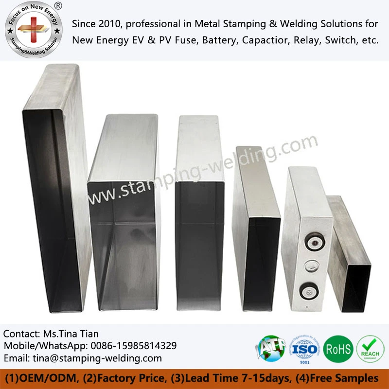
Solid-state and semi-solid cells run at 1–5 MPa external stack pressure and grow 1.5–3 % in stack thickness over 3,000 cycles, so the metal enclosure is a preloaded structural frame, not a container. Apollo forms these enclosures from 5052-H32 / 6061 aluminum on 8–12 station progressive deep drawing dies that hold wall thickness at 0.80 ±0.03 mm after ironing and raise sidewall yield strength by roughly 30 % through controlled cold work, then closes them with alumina-ceramic / modified-PEEK insulated cover plates validated at helium leak <1×10⁻⁹ Pa·m³/s and 2.5 MPa burst.
Stack Pressure and Swell Force: The Mechanical Load Case Behind the Enclosure Spec
Sulfide solid electrolytes need 2–5 MPa of maintained stack pressure; oxide-based systems sit at 1–3 MPa; semi-solid (in-situ gel) cells run at 0.3–1.0 MPa. On top of that preload, cyclic lithiation adds 1.5–3 % reversible thickness growth per full SOC window, and 2–4 % cumulative growth after 2,000 cycles at 25 °C / 1C.
That combination defines three hard requirements for the aluminum shell:
Hoop stiffness: mid-span sidewall deflection under 1.0 MPa internal pressure must stay below 0.25 mm on a 174 × 71 × 204 mm prismatic format; unreinforced 0.80 mm 5052-H32 measures 0.35 mm in FEA, which is why rib geometry or a 1.0 mm blank is specified above 200 Ah.
Preload retention: residual stack pressure after 10,000 h at 60 °C must stay ≥70 % of the initial value. With 5052-H32 held at ≤0.5 × Rp0.2 (≈98 MPa), creep strain stays under 0.2 %; exceeding 0.7 × Rp0.2 pushes creep past 0.6 %, and the cell loses contact pressure.
Burst margin: burst pressure ≥2.5 MPa (25 bar) against a vent disc calibrated to open at 0.7–1.0 MPa, giving a 2.5:1 margin between vent activation and shell rupture.
Design teams that treat the case as packaging rather than structure see capacity fade accelerate 8–15 % after 1,500 cycles, because pressure loss at the electrode/electrolyte interface raises interfacial resistance from ~8 Ω·cm² to >25 Ω·cm².
Material Selection: 5052-H32 vs 6061-T6 for Deep-Drawn Enclosures
5052-H32 is the default for deep-drawn prismatic shells; 6061 is selected when post-form machining, threaded ports, or T6 strength (276 MPa) matter and the budget accepts a solution heat-treat step.
| Property | 3003-H14 | 5052-H32 | 6061-O (as-drawn) | 6061-T6 (post-age) |
| Rp0.2 yield (MPa) | 145 | 195 | 55 | 276 |
| Rm tensile (MPa) | 150 | 230 | 124 | 310 |
| Elongation A50 (%) | 8–10 | 12–18 | 22–25 | 12 |
| Limiting draw ratio (LDR) | 2.05 | 2.15 | 2.25 | not formable |
| Thermal conductivity (W/m·K) | 155 | 138 | 180 | 167 |
| Electrical conductivity (% IACS) | 41 | 35 | 47 | 43 |
| Mg content/weld cracking risk | low / none | 2.5 % / low | 1.0 % / low | 1.0 % / hot cracking without 4043 filler |
| Typical application | small cell cans | structural EV + ESS shells | deep draw then age | machined prototype housings |
Three points drive the choice:
Cold work gain: 5052-H32 drawn with a 12–18 % ironing reduction work-hardens to ≈250 MPa yield at the sidewall, a ~30 % increase over the incoming coil, without an anneal step.
Corrosion: 5052 resists pitting in condensation cycles better than 6061; 6061-T6 shells require chromate-free conversion coating (Cr-free, RoHS/REACH compliant) before epoxy powder coating.
Weldability: laser welding 6061-T6 cover-to-shell joints without 4043 or 5356 filler produces solidification cracking at >0.6 % Mg₂Si eutectic; 5052 welds sound at 60–120 mm/s with a 2–4 kW fiber laser and no filler.
Request Free DFM Evaluation & Quote
Multi-Station Progressive Deep Drawing: Draw Ratio, Wall Thinning and Datum Tolerance
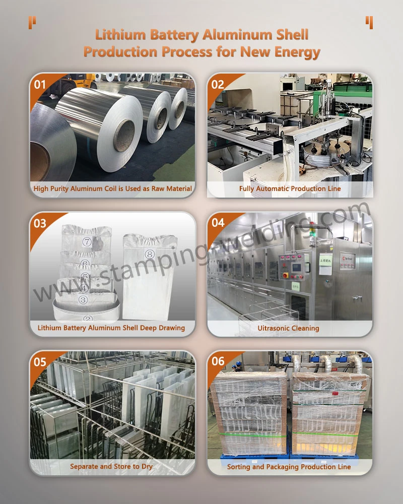
A 204 mm tall prismatic shell cannot be produced in one hit. Apollo runs 8–12-station progressive dies with intermediate annealing and a final ironing ring; every parameter below is a controlled variable with an SPC chart attached.
| Process variable | Target window | Verification method |
| Blank thickness | 0.80 / 1.00 mm, ±0.02 mm | Micrometer, 5-point per coil |
| Draw ratio per station | 1.25–1.45 | Die tryout report |
| Total LDR | ≤2.1 (single anneal) | first-piece CMM |
| Punch/die clearance | 1.05–1.10 × t | Feeler gauge, station audit |
| Blank holder force | 8–15 kN, nitrogen spring | Press load cell, per-stroke logging |
| Ironing reduction | 12–18 % | Ultrasonic wall thickness, 12 points |
| Minimum wall after ironing | ≥0.62 mm (thinning ≤22 %) | Ultrasonic + metallographic section |
| Inter-stage anneal | 345 °C × 1 h (5052), O-state reset | Furnace recorder, EN 10204 3.1 |
| Earring after trim | ≤0.15 mm | Dial indicator, 4-quadrant |
| ID profile tolerance | ±0.05 mm | CMM, Zeiss Contura, 0.9 µm + L/350 |
| Bottom flatness | ≤0.08 mm | CMM, 200-point scan |
| Surface roughness | Ra ≤0.8 µm | Mitutoyo SJ-210 |
Tooling: SKD11 punches at HRC 60–62, tungsten carbide ironing rings (0.4 µm Ra polished land), die life 1,000,000 strokes to first regrind, with dimensional re-qualification every 100,000 strokes. In-die riveting at station 11 fixes the vent-disc seat and terminal brackets, removing a secondary operation and holding positional tolerance at ±0.05 mm to the shell datum.
Cover Plate Terminal Sealing: Alumina Ceramic + High-Temperature Modified PEEK
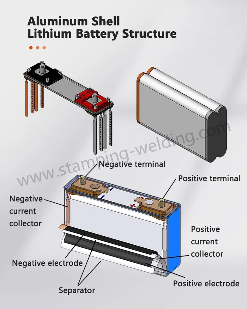
Terminal sealing fails in two ways: dielectric breakdown through the insulation, or a leak path opening at the metal/polymer interface after thermal cycling. The Apollo cover plate uses a hybrid: a 96 % Al₂O₃ ceramic ring carrying creepage and tracking resistance, compression-sealed inside a 30% glass-fiber-modified PEEK overmold that absorbs the CTE mismatch (alumina 7.2 ×10⁻⁶/K vs aluminum 23 ×10⁻⁶/K).
| Sealing architecture | Dielectric strength | Continuous use temp | Helium leak rate | Failure mode to control |
| 96 % alumina + Ag72Cu28 active braze (780 °C) | 15–20 kV/mm | 800 °C | <1×10⁻¹⁰ Pa·m³/s | brittle ring under >0.3 % strain |
| Glass-to-metal (borosilicate) | 20–30 kV/mm | 400 °C | <1×10⁻¹¹ Pa·m³/s | Cracks under mechanical shock |
| Modified PEEK (30 % GF) injection over terminal | 20–25 kV/mm (ASTM D149, 1 mm) | 250 °C RTI, Tg 143 °C | <1×10⁻⁹ Pa·m³/s | Hydrolysis above 200 °C steam |
| PPS (40 % GF) | 18–20 kV/mm | 200 °C | <1×10⁻⁸ Pa·m³/s | low impact toughness at −40 °C |
| Epoxy potting | 15–18 kV/mm | 150 °C | not hermetic | CTE-driven debonding |
Qualification targets on the finished cover plate:
Flammability: UL 94 V-0 at 0.8 mm; glow-wire flammability index 960 °C (IEC 60695-2-12).
Tracking: comparative tracking index CTI ≥600 V (IEC 60112), creepage distance ≥8 mm at 1,000 V DC working voltage.
Dielectric: 4.2 kV DC / 60 s between terminal and cover, leakage <1 mA, partial discharge <5 pC at 1.5 kV.
Thermal cycling: −40 °C to +125 °C, 1,000 cycles (IEC 62660-2 profile), post-cycle helium leak still <1×10⁻⁹ Pa·m³/s.
Rail and ESS compliance: EN 45545-2 R22/R23 HL3 where applicable; IEC 62619 / UL 1973 system-level testing with the customer's module.
For high-current covers, the plate can integrate a laminated busbar (0.3 mm C1100 copper / 0.05 mm PET dielectric, molecular diffusion welded terminations) with measured stray inductance <10 nH at 1 MHz, 300 A continuous rating, temperature rise <30 K, and contact resistance <0.1 mΩ per joint. Where a Cu-to-Al transition is needed at the terminal, molecular diffusion welding keeps the CuAl₂ intermetallic layer under 2 µm; resistance silver brazing (Ag72Cu28, 780 °C) is the fallback for section sizes above 6 mm².
Download Battery Enclosure Design Specification
Cover-to-Shell Closure: Laser Welding, Helium Leak Test and 2.5 MPa Burst
The closure joint is the last barrier between the electrolyte and ambient humidity. Sulfide electrolytes generate H₂S above 30 ppm when exposed to moisture at >1 % RH, so the leak spec is not cosmetic.
Weld process: 1070 nm fiber laser, 2–4 kW, wobble head at 120 Hz, travel 60–120 mm/s, argon shielding at 15 L/min. Target penetration 0.9–1.2 mm on a 0.80 mm wall, weld width 1.2–1.6 mm, concavity ≤0.1 mm.
Porosity control: metallographic section every 250 pieces, acceptance ≤1 % pore area and no pore >0.15 mm; keyhole instability is suppressed by power ramp-down over the last 8 mm of the seam.
Leak test: helium mass spectrometry, 100 % in-line, sniffing and vacuum-chamber modes, acceptance <1×10⁻⁹ Pa·m³/s (≈1×10⁻⁸ mbar·L/s), result logged per serial number.
Burst test: 2.5 MPa hydrostatic ramp at 0.1 MPa/s, 30 s hold, per IEC 62660-2 abuse test protocol; acceptance is no rupture, permanent deformation <0.3 %.
Fatigue: 0–1.0 MPa pressure cycling, 100,000 cycles at 1 Hz, post-test leak still <1×10⁻⁹ Pa·m³/s.
Vent integration: scored vent disc opens at 0.7–1.0 MPa with ±5 % scatter, verified on 30-piece burst lots.
External Insulation: Epoxy Powder Coating vs Heat-Shrink Sleeving
Once the shell is closed, the outer surface carries an 800–1,500 V DC potential relative to the module frame in a 1,500 V pack architecture. Insulation selection follows the pack voltage, not habit.
| Insulation method | Thickness | Dielectric strength | Temp range | Adhesion/durability |
| Epoxy powder coating (electrostatic, 200 °C cure) | 60–120 µm | >15 kV/mm (IEC 60243-1) | −40 to +150 °C | ISO 2409 Class 0, 500 h salt spray (ISO 9227) |
| Heat-shrink PET sleeve | 100–150 µm | 12 kV/mm | −40 to +125 °C | lifts above 105 °C, traps condensate |
| Anodizing, Type II | 8–12 µm | ~20 V/µm | up to 200 °C | brittle, cracks at bend radius <3t |
| Parylene C (vapor deposition) | 10–25 µm | 200 kV/mm | −200 to +130 °C | Poor abrasion resistance, 8× cost |
Epoxy powder coating is specified for module-level enclosures: 80 µm nominal, pinhole-free at 3 kV DC spark test, adhesion Class 0 after 1,000 h damp-heat (85 °C / 85 % RH), and dielectric withstand 4 kV AC / 60 s per IEC 61189. Heat-shrink sleeving is reserved for low-volume prototypes where tooling cost must stay under USD 500.
PPAP Level 3, Tooling Life and T1 Lead Time: What Buyers Should Specify
Procurement teams lose time when the RFQ does not fix the quality deliverable. Apollo quotes against PPAP Level 3 by default for automotive programs:
Deliverables: 18-element PPAP, full ISIR dimensional report (CMM, 100 % of drawing characteristics), material certificate EN 10204 3.1, weld macro-sections, helium leak records, coating thickness per ISO 2360, IMDS entry, RoHS/REACH declaration.
Capability: Cpk ≥1.33 on the three critical characteristics (ID width, height to terminal datum, wall thickness at the ironed zone); MSA gauge R&R ≤10 %.
Tooling: progressive die owned by the customer, serial-numbered, stored under IATF 16949 tooling control, die life guaranteed to 1,000,000 strokes with free regrind at 500,000.
Schedule: T1 sample 15–25 working days after die design freeze; PPAP Level 3 submission 6–8 weeks after T1 approval; production ramp 4–6 weeks.
Traceability: each shell is laser-marked with a DataMatrix code linked to die station, coil heat number, weld parameters, and leak test value, retained for 15 years.
FAQ
What is the T1 lead time for a custom deep-drawn solid-state battery aluminum case?
15–25 working days after die design freeze for T1 samples, including first-piece CMM report and weld macro-sections. PPAP Level 3 submission follows 6–8 weeks after T1 approval; production ramp takes another 4–6 weeks. Tooling design itself adds 10–15 days before the die build starts.
How many strokes does a progressive deep drawing die run before dimensional drift exceeds ±0.05 mm?
1,000,000 strokes to first regrind with SKD11 punches and carbide ironing rings, based on 5052-H32 at 12–18 % ironing reduction. Dimensional re-qualification runs every 100,000 strokes; wall thickness is monitored by ultrasonic gauge every 500 pieces to hold thinning under 22 %.
Can coating thickness and helium leak rate be verified on every production lot?
Yes. Coating thickness is measured by eddy current per ISO 2360 at five points per part, 60–120 µm acceptance, with 3 kV DC spark testing for pinholes. Helium mass spectrometry runs 100 % in-line at <1×10⁻⁹ Pa·m³/s, and each result is stored against the laser-marked DataMatrix serial number for 15 years.
contact us