


Why Early DFM Review Can Reduce Custom Busbar Costs By 30%
Sep 14, 2026
Custom busbar DFM optimization can reduce production cost by up to 30% when bend radii, hole spacing, material utilization, and manufacturing processes are reviewed before tooling begins. For copper busbars, early engineering review also determines whether progressive stamping, laser cutting, bending, or a combined process provides the best balance of tooling cost, cycle time, dimensional control, and production volume.
For a Busbar Manufacturer China sourcing program, the lowest quoted piece price is not necessarily the lowest total manufacturing cost. Tooling investment, scrap rate, secondary operations, inspection requirements, and annual production volume must be evaluated together.
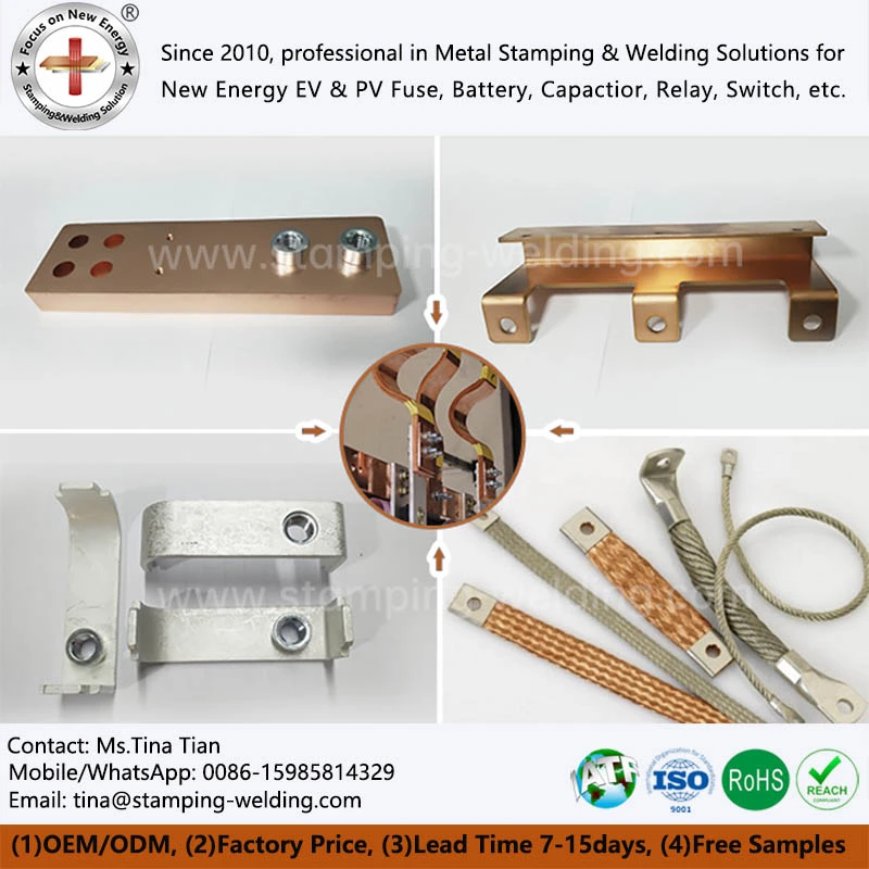
1. Copper Busbar DFM: Bend Radius and Hole Spacing
1.1 Copper Bend Radius Based on Material and Thickness
Copper is highly conductive but its forming behavior varies with material grade, temper, thickness, grain direction, and bending method. An unnecessarily tight bend can increase springback variation, surface deformation, cracking risk, and tooling complexity.
For a stamped copper busbar, engineers should define the minimum inside bend radius according to the actual copper grade and thickness rather than applying one fixed value across all designs.
| DFM Factor | Poor Design Approach | DFM-Oriented Approach |
|---|---|---|
| Inside bend radius | Extremely tight radius | Radius matched to material/thickness |
| Bend location | Close to holes | Adequate edge distance |
| Multiple bends | Conflicting forming directions | Consistent forming sequence |
| Springback | Ignored during CAD design | Compensated in tooling |
| Forming process | Selected after design release | Selected during DFM review |
1.2 Hole-to-Edge Distance Affects Tooling and Part Stability
The distance between a punched hole and the busbar edge directly affects material deformation around the hole. Excessively small edge distances can cause distortion, burr concentration, or local cracking during punching and forming.
A DFM review should therefore evaluate:
- Hole diameter versus copper thickness
- Hole-to-edge distance
- Hole-to-bend distance
- Hole pitch and positional tolerance
- Fastener clearance and assembly access
- Punch and die accessibility
For high-volume production, these dimensions should be optimized together with the progressive die layout rather than independently.
1.3 DFM Should Start Before Tooling
Changing a hole position after progressive-die construction can require punch replacement, insert modification, or even die redesign. Reviewing the 2D drawing and 3D CAD model before tooling locks the critical geometry into a manufacturable process.
Request Free Busbar DFM Review
2. Progressive Stamping vs Laser Cutting for Copper Busbars
2.1 Process Selection by Production Volume
Stamping and laser cutting serve different production requirements. Laser cutting avoids dedicated blanking dies and is useful for prototypes, engineering validation, and low-volume production. Progressive stamping generally becomes more economical as annual volume increases because several operations can be integrated into one die.
| Factor | Progressive Stamping | Laser Cutting |
| Initial tooling | Higher | Low |
| Prototype flexibility | Lower | High |
| High-volume cycle time | Low | Higher |
| Repeated geometry | Excellent | Excellent |
| Complex punched holes | Excellent | Good |
| Tooling amortization | Requires volume | Minimal |
| Prototype modification | Slow after tooling | Fast |
| Material utilization | Optimized through nesting | Depends on layout |
2.2 When Laser Cutting Reduces Total Cost
For a new busbar project without confirmed annual volume, laser cutting can avoid premature tooling expenditure. It also allows rapid geometry changes during electrical and mechanical validation.
Typical applications include:
- Prototype copper busbars
- EV battery pack development samples
- ESS connection prototypes
- Low-volume power electronics
- Design validation before progressive-die investment
Once demand becomes stable, the same geometry can be reviewed for progressive stamping and automated bending to reduce piece cost.
2.3 Stamping Becomes More Attractive at Higher Volume
A Cost Reduction Metal Stamping strategy should consider the complete manufacturing route rather than stamping price alone. Progressive dies can combine blanking, piercing, embossing, bending, and forming into sequential stations.
The economic model should include:
- Annual production volume
- Tooling amortization
- Copper utilization
- Scrap recovery
- Press cycle time
- Secondary bending operations
- Inspection cost
- Labor and automation requirements
Unsure whether your annual volume justifies a progressive stamping die?
Get Process Selection & Cost Review

3. Copper Utilization and Tooling Design for Cost Reduction
3.1 Strip Layout Directly Affects Material Cost
Copper often represents a significant proportion of the total busbar cost. Improving strip utilization can therefore produce savings without changing electrical performance.
During DFM review, engineers evaluate:
- Part-to-part pitch
- Carrier width
- Nesting orientation
- Scrap bridges
- Grain direction
- Common-strip layouts
- Coil width selection
A small improvement in strip utilization becomes significant when multiplied by hundreds of thousands or millions of parts.
3.2 Integrating Secondary Operations Into the Die
Separate drilling, punching, or forming operations increase handling and inspection requirements. Where geometry permits, these operations can be incorporated into a progressive die.
For example, a production sequence may integrate:
Blanking → Piercing → Embossing → Bending → Forming → Cut-off
This reduces manual handling and improves positional consistency between features.
3.3 Tooling Design Must Match Copper Forming Behavior
Die clearance, punch geometry, forming sequence, and stripping force must be considered together. Copper burr formation and deformation are affected by material thickness, hardness, cutting clearance, and tool condition.
For automotive programs, process capability should be established for critical dimensions rather than relying solely on final-product inspection.
4. DFM Optimization for OEM Busbar Production
4.1 Drawing Review Before Sample Production
A practical Custom Busbar DFM Optimization review starts with the customer's 2D drawing and 3D CAD data. Engineering checks should cover:
- Electrical connection surfaces
- Hole and slot geometry
- Bend sequence
- Minimum forming radius
- Material thickness
- Dimensional tolerances
- Welding locations
- Plating or surface-treatment requirements
- Assembly interfaces
The objective is to identify manufacturing risks before they become tooling changes or production defects.
4.2 Prototype-to-Mass-Production Conversion
For OEM programs, prototype manufacturing should not use a process that cannot later support production volume. A laser-cut prototype may validate geometry quickly, but the production route may require stamping, bending, welding, plating, or automated inspection.
A suitable DFM strategy therefore considers both T1 sample validation and the intended mass-production process.
4.3 Engineering Changes Should Be Costed Before Release
A dimensional change that appears minor on a CAD model can have a significant manufacturing impact. Moving a hole may affect the die station sequence; changing a bend may require a new forming insert; reducing material thickness may change springback and current-carrying characteristics.
Early DFM review identifies these consequences before the drawing reaches production release.
5. China Busbar Manufacturer: DFM Review to Production
A capable Busbar Manufacturer China program should connect engineering review directly with tooling, production, inspection, and delivery. Separating these stages can create communication gaps between the drawing and the final production process.
For custom copper busbars, an integrated factory workflow can include:
- CAD and drawing review
- DFM and process analysis
- Tooling design and fabrication
- Laser-cut or stamped prototype
- Dimensional and electrical validation
- Production process approval
- Progressive stamping and forming
- Welding or surface treatment where specified
- Final inspection and traceability
For automotive supply chains, quality planning can be aligned with IATF 16949, ISO 9001, PPAP documentation, process capability studies, and customer-specific inspection requirements.

6. Practical DFM Checklist for Custom Copper Busbars
6.1 Before Tooling Release
- C1100/T2 copper grade and thickness confirmed
- Bend radius checked against material thickness
- Hole-to-edge distance verified
- Critical dimensional tolerances identified
- Stamping or laser process selected
- Strip utilization calculated
- Progressive-die station sequence reviewed
- Secondary operations minimized
- Inspection method defined
- Annual volume used for tooling cost analysis
6.2 Before Mass Production
- T1 samples dimensionally verified
- Electrical connection surfaces inspected
- Critical characteristics identified
- Process capability evaluated
- Tooling condition monitored
- Inspection records established
- Production and traceability requirements confirmed
The most effective DFM decisions are made before the first production die is built. For copper busbars, geometry, material utilization, forming sequence, tooling structure, and production volume should be evaluated as one manufacturing system.
FAQ
DFM review should begin after the initial 2D drawing and 3D CAD model are available, before tooling design is finalized. Reviewing bend radius, hole spacing, tolerances, strip layout, and process selection at this stage minimizes later die modifications and engineering changes.
Progressive stamping is generally better for stable, higher-volume production because tooling cost can be amortized across large quantities. Laser cutting is more suitable for prototypes, design validation, frequent geometry changes, and low-volume requirements where dedicated tooling is not economical.
Cost reduction comes from several factors: improved strip utilization, fewer secondary operations, optimized die stations, appropriate tolerances, reduced tooling revisions, and selecting stamping or laser cutting according to annual volume. These factors can collectively reduce manufacturing cost by up to 30% in suitable designs.
Yes. A DFM review can evaluate material, bend geometry, hole spacing, dimensional tolerances, manufacturing sequence, and tooling requirements before production tooling begins. This allows engineering risks and potential cost drivers to be identified before the tooling investment.
A 2D manufacturing drawing, 3D CAD model, copper grade and thickness, annual volume, required tolerances, electrical requirements, surface-treatment specifications, and target application provide the engineering information needed for process and cost evaluation.
Contact Us


