The Working Principle And Application Development Of Laminated Busbars: Low-Inductance Design Drives Upgrades in High-Power Power Electronics Interconnections
Oct 18, 2026
As sectors such as new energy vehicles, energy storage systems, industrial variable-frequency drives, and telecommunications power supplies evolve toward higher power, higher frequency, and greater integration, the demands on electrical interconnection systems-specifically regarding current-carrying capacity, parasitic inductance, thermal management, and electromagnetic compatibility-continue to rise. Laminated busbars, which consist of alternating conductive and insulating layers, form compact electrical interconnection structures. By shortening current loops, reducing parasitic parameters, and enhancing power transmission efficiency within equipment, they have become essential components in modern power electronics.
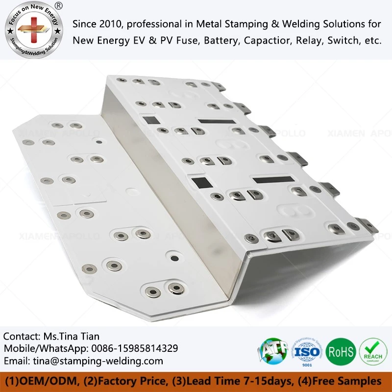
Laminated busbars utilize a multi-layer composite structure to achieve electrical isolation
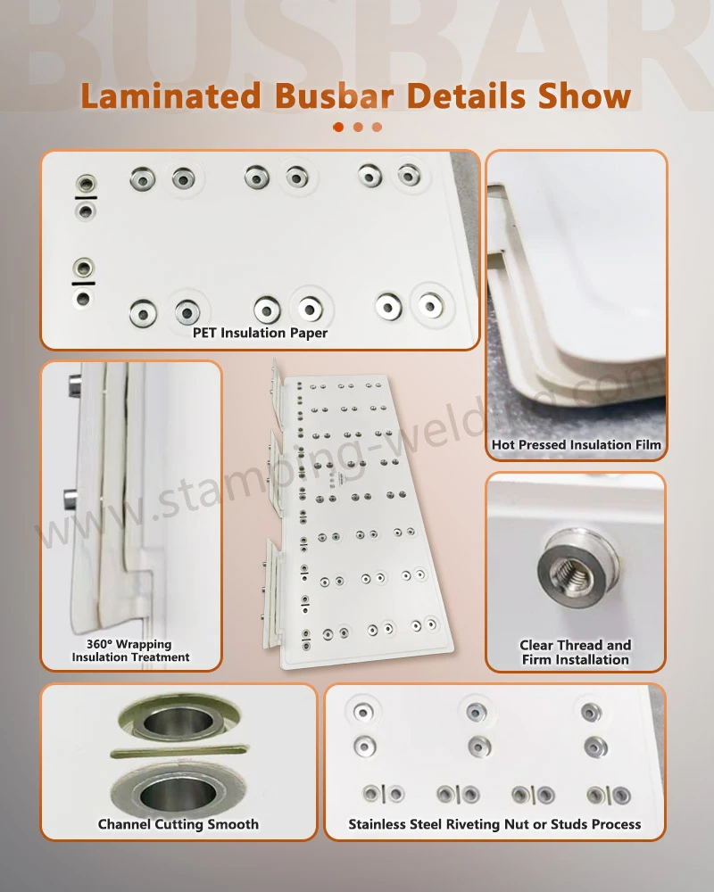
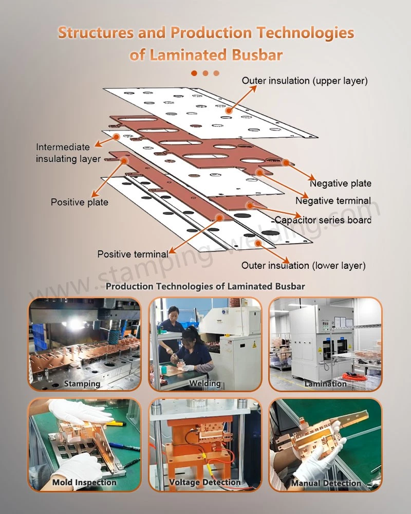
Typically, laminated busbars are composed of conductive materials-such as copper or aluminum-and insulating materials, including polyimide, PET, or epoxy resin. Conductive layers of opposing polarity are stacked according to specific design requirements, with insulating media providing electrical isolation. This creates a stable, compact, and planar current path within a limited installation space.
Compared to traditional single-layer busbars or cable-based connections, the laminated structure allows for the placement of positive and negative conductors in proximity, thereby shortening the current path. The thickness, width, spacing, and number of conductive layers are determined based on factors such as rated current, operating voltage, allowable temperature rise, and available equipment space.
Connection zones are equipped with mounting holes, terminals, or other interfaces, enabling integration with power modules, capacitors, switching devices, filters, and various other electrical components. For space-constrained power electronic equipment, laminated busbars allow multiple electrical paths to be integrated into a small footprint, facilitating an optimized internal layout.
Low inductance is a core operational principle of laminated busbars
One of the most significant technical advantages of a laminated busbar is its ability to reduce the parasitic inductance of the current loop. In equipment such as inverters, variable-frequency drives, and switching power supplies, power devices undergo frequent, high-speed switching. This results in high rates of current change, where parasitic inductance within the connection path can generate significant voltage spikes.
When positive and negative conductive layers are arranged in a tightly laminated structure, the distance between the two opposing current paths is substantially reduced. According to the principle of electromagnetic field superposition, the magnetic fields generated by two current-carrying conductors can partially cancel each other out, thereby reducing the effective inductance of the entire circuit loop.
A low-inductance structure helps mitigate overvoltage and ringing phenomena during high-speed switching, leading to more stable operation of power devices while simultaneously reducing switching losses and electromagnetic interference (EMI). In high-speed computing equipment, laminated bus bars-used for circuit boards or backplanes-leverage short-distance, multi-layer planar connections to enhance the structural efficiency of high-current power delivery paths.
Planar Conductive Structures Improve Current Distribution
Beyond reducing loop inductance, the planar architecture of laminated bus bars improves how current is distributed within the conductors.
Traditional cables often require large bending radii, while dispersed single-layer bus bars can lead to longer connection distances and increased space consumption.
By carefully designing the width of the conductive layers and the placement of connection points, laminated bus bars create well-defined current paths, allowing for more compact power distribution within the equipment. For high-current DC systems, laminated bus bars used for power distribution backplanes minimize the need for complex, crisscrossing cable arrangements, thereby improving space utilization within the unit.
Under high-frequency operating conditions, factors such as the skin effect, proximity effect, and current coupling between conductors must be considered. Consequently, the spacing between layers, the thickness of the conductors, and the choice of materials in a laminated bus bar affect not only the rated current-carrying capacity but also the impedance characteristics at high frequencies.
Insulation Layers Provide Both Electrical Isolation and Mechanical Support
The insulating material within a laminated bus bar serves a purpose beyond merely preventing short circuits; it also facilitates layer positioning, provides mechanical support, and ensures voltage withstand capability.
Different operating voltages and environments impose specific requirements on insulating materials regarding heat resistance, dielectric strength, flame retardancy, and long-term reliability. During the design process, engineers must account for factors such as the voltage differential between conductors, creepage distances, electrical clearances, operating temperatures, and ambient humidity.
For telecommunications equipment, laminated bus bars used in cellular base station power distribution must reliably isolate multiple power paths within a confined space, while also maintaining thermal stability and insulation integrity during long-term, continuous operation.
Low Impedance and Thermal Management Affect Long-Term System Reliability
When high currents flow through a conductor, Joule heating occurs. Factors such as the conductor's cross-sectional area, material resistivity, the quality of connection interfaces, and the operating current all influence the overall temperature rise. Consequently, during the design phase of laminated busbars, it is essential to consider not only current-carrying capacity but also thermal management.
Copper, with its high electrical and thermal conductivity, is well-suited for power electronics applications that demand high current-carrying capacity. Aluminum, being less dense, offers advantages in equipment where lightweight design is a priority. The final material selection should be based on a comprehensive assessment of current ratings, available installation space, weight constraints, and manufacturing costs.
Connection terminals are also critical areas for thermal management. Whether using bolted, welded, or other types of connections, it is vital to maintain stable contact resistance to prevent localized poor contact, which can lead to abnormal heat generation.
In power distribution units (PDUs) used in servers, telecommunications, and data centers, busbars must withstand continuous current over long periods. Therefore, the reliability of their conductor dimensions, insulation structures, and connection interfaces must be rigorously verified through engineering analysis.
Laminated Structures Help Reduce Electromagnetic Interference (EMI)
High-speed power devices generate rapidly changing currents and voltages during operation, creating electromagnetic fields that can interfere with surrounding circuitry. By shortening the current loop between the positive and negative terminals, laminated busbars reduce the loop area, thereby mitigating radiated and conducted electromagnetic interference at the source.
This structure is highly valuable for equipment such as motor controllers, inverters, and high-frequency power supplies. For instance, a motor controller busbar must maintain stable power transmission under high-current, fast-switching conditions, while minimizing the impact of parasitic parameters on the performance of power devices.
For equipment requiring continuous high-speed data processing and high-power delivery, the structural design of the busbar must be coordinated with electromagnetic compatibility (EMC) requirements. An optimized lamination strategy can eliminate unnecessary current loops and provide a more stable electrical foundation for subsequent EMC design.
Planar Design Simplifies Internal Equipment Wiring
Traditional cable-based connections typically require individual steps-such as cutting, crimping, insulating, and securing-and necessitate dedicated space for routing cables within the equipment. Laminated busbars can be customized to fit the internal dimensions of equipment, allowing multiple connection paths to be integrated into predetermined positions.
In power supply systems, busbars can be used to interconnect various functional modules-such as rectifiers, inverters, capacitor banks, and output stages-replacing complex cabling with an integrated structure.
For equipment manufacturers, this design optimizes internal space, streamlines assembly, and ensures greater consistency during mass production. Furthermore, the clear, planar layout simplifies the identification of distinct electrical circuits, facilitating maintenance and repairs.
Laminated busbars are employed across a wide range of high-power applications
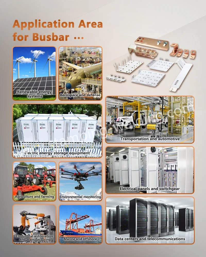
As power electronics technology evolves, the use of laminated busbars has expanded beyond traditional industrial power supplies into sectors such as new energy vehicles, rail transit, telecommunications power, data centers, and renewable energy generation.
In rail transit and high-power drive systems, busbars for four-quadrant power modules must be engineered based on the current paths and mechanical constraints of the power modules, while also meeting requirements for electrical insulation, thermal management, and vibration resistance.
In telecommunications infrastructure, laminated busbars prioritize multi-channel power distribution, space efficiency, and long-term operational reliability. For internal power distribution in network equipment-such as in router backplanes-the design must account for backplane dimensions, connection interfaces, and modular layouts.
Moreover, laminated busbars can be tailored to the specific mechanical dimensions and electrical parameters of various devices. Applications such as those found in stage lighting systems demand compact wiring and multi-channel power connectivity, with the final structure determined by the available internal space and load requirements.
In network equipment and high-speed computing systems, laminated busbars utilize a multi-layer conductor structure to achieve high-density power connections, significantly reducing the space consumed by traditional cabling.
Laminated busbars are trending toward higher levels of integration and precision manufacturing
Industry trends indicate that laminated busbars are evolving from simple conductive connectors into highly integrated electrical structures. Future product designs will increasingly focus on low parasitic inductance, low contact resistance, thermal management, insulation reliability, and mechanical integration capabilities.
In the manufacturing phase, there will be a greater emphasis on process control-including precision stamping, conductor forming, insulation material lamination, interlayer positioning, welding, and automated assembly. For high-power and high-frequency applications, busbars must go beyond meeting basic current-carrying requirements; they must also undergo multi-dimensional validation-covering electrical, thermal, and mechanical aspects-to ensure long-term operational stability.
When selecting a laminated busbar solution, engineering procurement professionals and equipment R&D teams are advised to provide key specifications in advance, such as rated current, operating voltage, peak current, operating frequency, installation dimensions, conductor and insulation materials, connection methods, and temperature rise limits. Utilizing comprehensive engineering parameters for structural design and process evaluation allows for more precise determination of conductor specifications, insulation schemes, and the overall laminated structure.
If you have requirements for custom laminated busbars, copper busbars, or electrical connection components for new energy applications, please submit your product drawings, 3D files, or technical specifications. Our engineering team is available to discuss materials, structural design, manufacturing processes, and volume production strategies to facilitate detailed engineering assessments and formal inquiries.
contact us