5000A+ Electrolyzer Busbar: Why Flexible Laminated Flat Copper Busbars Matter For Thermal Expansion Compensation
Sep 07, 2026
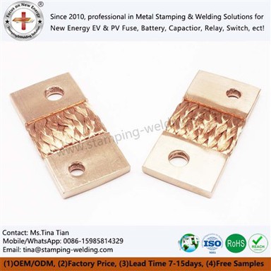
A Flexible Copper Expansion Joint is used where high-current electrical connections must accommodate thermal movement, vibration, and installation tolerances. For electrolyzers and heavy smelting equipment operating above 5000A, a rigid copper connection can transfer thermal expansion directly into terminals, bolts, and equipment interfaces. A Flexible Laminated Flat Copper Busbar provides a more flexible current-carrying connection, allowing controlled movement while maintaining a low-resistance electrical path between high-current components.
For these applications, multilayer copper foil provides a flexible current path while molecular diffusion welding joins the foil layers into a low-resistance conductive assembly. A 0.1mm copper foil configuration can be stacked to achieve the required conductive cross-section while retaining bending flexibility.
The engineering objective is not simply to increase copper cross-section. The connection must balance current capacity, thermal expansion compensation, contact pressure, electrical resistance, mechanical movement, and available installation space.

0.1mm Copper Foil + Molecular Diffusion Welding for 5000A+ Connections
For a High Current Electrolyzer Busbar, the copper foil structure is normally determined from the required continuous current, allowable temperature rise, connection dimensions, and mechanical movement.
The use of thin copper foil allows multiple layers to work in parallel. Compared with a single thick copper plate, the layered structure can provide greater flexibility in the direction where thermal expansion or equipment movement needs to be absorbed.
The key manufacturing step is molecular diffusion welding. Instead of relying on solder or a conventional filler metal, controlled heat and pressure are used to establish metallurgical bonding between copper foil layers. The process must maintain consistent pressure and temperature across the bonding area; otherwise, local bonding variations can increase electrical resistance and create uneven heat generation.
For procurement and engineering teams, three parameters should be confirmed before production:
- Foil thickness: 0.1mm foil can be used as a basis for multilayer construction where flexibility is required.
- Layer count: determined according to current capacity, temperature rise, overall thickness, and installation space.
- Welding area: sized according to the required current path and terminal interface.
The final structure should be validated by electrical resistance and temperature-rise testing rather than selected only from nominal current values.
Need a flexible copper connection for 5000A+ electrolyzer current?
Request 5000A+ Copper Expansion Joint Engineering Review

Low-Resistance Copper Shunt Design for 5000A+ Power Transmission
A Diffusion Welded Copper Shunt must maintain a stable current path across both the flexible foil section and the terminal connection. At several thousand amperes, even a small increase in connection resistance produces additional I²R losses and localized heating.
For this reason, resistance control should cover the complete electrical path rather than the copper foil alone. The interface between the expansion connector and the equipment terminal is particularly important because insufficient contact pressure, uneven surfaces, oxidation, or inadequate contact area can increase voltage drop.
The design should therefore consider:
| Engineering factor | Selection consideration |
|---|---|
| Continuous current | 5000A+ operating requirement |
| Copper foil | 0.1mm foil or other specified thickness |
| Layer count | Based on required conductive cross-section |
| Flexible section | Required thermal movement and vibration absorption |
| Terminal area | Sufficient contact area for the operating current |
| Connection method | Bolted or specified equipment interface |
| Validation | Resistance and temperature-rise testing |
The practical target is a connection with consistent resistance throughout the production batch. Resistance testing at defined points can help identify abnormal bonding or terminal-contact conditions before installation.
This approach also helps quantify the electrical impact of the connector. Instead of describing a product simply as "high conductivity," procurement specifications can define measurable resistance, temperature-rise, dimensional, and inspection requirements.
Thermal Expansion Compensation with 5000A+ Flexible Copper Expansion Joints
A Flexible Copper Expansion Joint is particularly useful when copper conductors connect equipment that operates at different temperatures or experiences repeated thermal cycling. Electrolyzer systems and heavy smelting equipment can generate substantial heat around high-current connection points, creating dimensional movement that a rigid copper plate may not absorb effectively.
The flexible section allows controlled movement while maintaining the electrical path. Its geometry should be considered together with the expected expansion direction, available installation clearance, connection-point distance, and required flexibility.
For engineering review, the following dimensions should be defined on the drawing:
- Overall connector length
- Copper foil width
- Total foil thickness
- Terminal thickness
- Bolt-hole diameter
- Hole center distance
- Flexible section length
- Bending direction
- Installation clearance
The connector should not be forced into position during assembly. If the flexible section is too short, installation can introduce excessive mechanical stress into the terminals. If it is unnecessarily long, the connector may interfere with surrounding components.
A 3D installation model is therefore useful during the quotation stage, particularly for irregular connection paths or restricted equipment layouts.
Custom Forming for Irregular High-Current Connection Paths
Not every high-current connection can use a flat rectangular conductor. Equipment layouts may require offset terminals, stepped profiles, different connection heights, or a flexible section positioned between fixed mounting points.
For these applications, the High Current Electrolyzer Busbar can be designed with customized terminal geometry and foil-stack dimensions. CNC precision cutting can be used for prototype development and irregular profiles, while the production method can be selected according to geometry, quantity, and dimensional requirements.
The engineering review should focus on the actual interface rather than adapting a standard connector. Drawing data should define the terminal hole pattern, connection orientation, foil width, overall length, and flexible-zone position.
Where copper foil is used for the flexible section, the transition between the rigid terminal and flexible area also requires attention. A controlled transition reduces unnecessary concentration of mechanical stress and helps maintain repeatable assembly geometry.
For OEM projects, a 2D drawing, 3D CAD model, existing sample, or equipment interface dimensions can provide sufficient information for an initial design review.

Quality Validation for 0.1mm Multilayer Copper Foil Assemblies
Production validation should verify both electrical and mechanical characteristics. For a Diffusion Welded Copper Shunt, the inspection plan can include material verification, foil thickness measurement, dimensional inspection, diffusion-welded area inspection, electrical resistance testing, and temperature-rise testing.
For high-current projects, sample validation should be completed before mass production. The Flexible Laminated Flat Copper Busbar production control plan should define critical dimensions and process parameters so that changes in foil stacking, welding, cutting, or terminal forming can be detected before shipment.
Where automotive or other controlled supply chains require formal documentation, quality procedures can be aligned with IATF 16949 and project-specific PPAP requirements.
FAQ: 5000A+ Copper Expansion Joint Engineering Questions
Q: How is the copper foil layer count determined for a 5000A+ electrolyzer connection?
A: Layer count is determined from continuous current, allowable temperature rise, foil thickness, foil width, available installation space, and required flexibility. The final configuration should be verified through electrical resistance and temperature-rise testing.
Q: Why use 0.1mm copper foil for a flexible high-current connector?
A: Thin copper foil allows multiple conductive layers to form a flexible assembly. The layered structure can accommodate mechanical movement more effectively than a single thick copper plate while providing the required conductive cross-section.
Q: Can the terminal geometry of a diffusion-welded copper shunt be customized?
A: Yes. Terminal thickness, hole diameter, hole spacing, orientation, overall length, foil width, and flexible-section geometry can be specified according to the equipment interface and installation requirements.
Q: What information should be provided for a 5000A+ copper expansion joint quotation?
A: Provide the continuous current, operating voltage, allowable temperature rise, connection-point dimensions, terminal hole pattern, overall length, available installation space, preferred copper material, and expected annual or project quantity.
Contact Us
For 5000A+ electrolyzer and heavy-smelting applications, contact us for a customized Flexible Laminated Flat Copper Busbar or copper expansion connection designed around your current, thermal movement, and installation requirements.