The Application And Technical Development Of Heat-Shrinkable Insulation Materials For Busbar Insulation Protection in Substations
Oct 02, 2026
As substation voltage levels, equipment integration, and operating environments become increasingly complex, insulation protection for busbars, connection points, and electrical clearances has become a critical component of safe substation operation. This is particularly important for the retrofitting of aging substations, outdoor substations, and facilities located in environments characterized by high humidity, salt spray, or pollution. In such settings, exposed conductors are susceptible to factors such as condensation, contamination, ice accretion, contact with foreign objects, and corrosion; consequently, reliable insulation materials are required to mitigate operational risks.
Radiation-crosslinked heat-shrinkable materials are a class of polymer insulation materials modified via crosslinking to exhibit heat-shrinkage properties. Following specific processing, these materials shrink in a predetermined direction when heated, forming a stable insulating layer over the conductor. Compared to traditional insulation methods, heat-shrinkable structures readily conform to the shapes of busbars and the spatial variations of connection points, offering excellent adaptability for applications such as substation busbars, switchgear, and cable accessories.
In practical applications, the primary value of heat-shrinkable insulation materials lies not merely in covering exposed conductors, but in creating a continuous insulation barrier that enhances isolation between live components and the external environment, while minimizing direct contact between conductors and moisture, contaminants, or foreign objects. For space-constrained switchgear, these materials can also be integrated into insulation designs to optimize electrical clearances and internal equipment layouts.
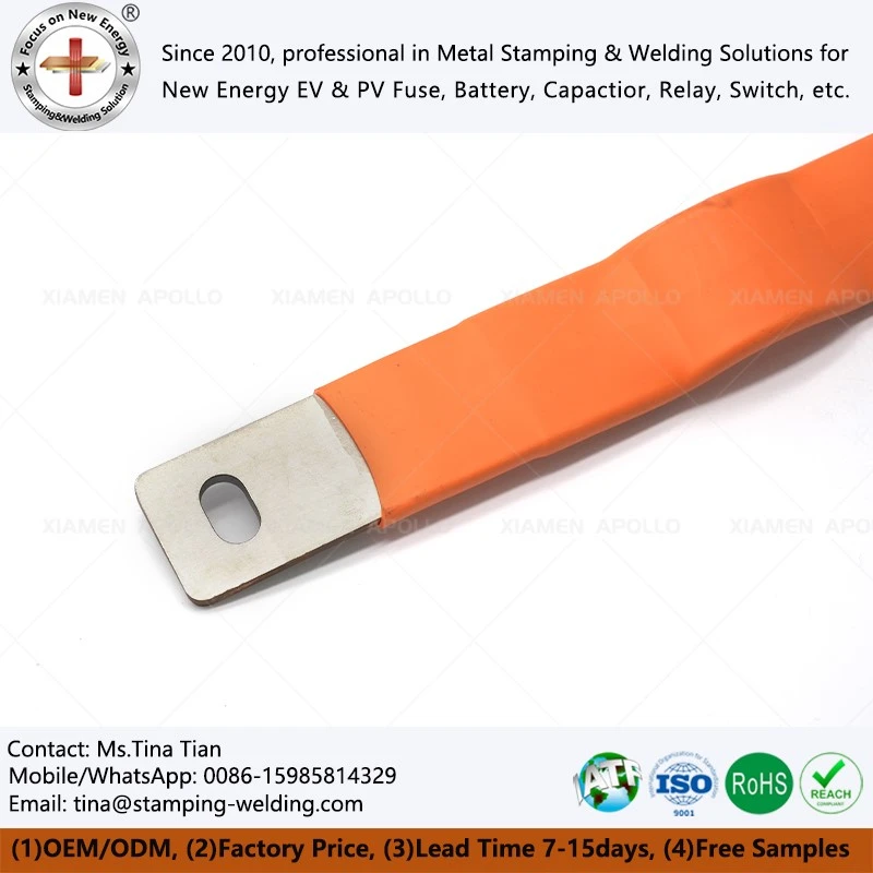
Common Heat-Shrinkable Insulation Materials and Structural Forms in Substations
Heat-shrinkable products used for substation insulation protection primarily include heat-shrinkable busbar insulation tubing, composite heat-shrinkable insulation tape, insulation shrouds, cable termination accessories, and creepage-enhancing structures. As these products vary in structural form and application, selection should be based on factors such as voltage level, conductor dimensions, environmental conditions, installation method, and mechanical requirements.
Heat-shrinkable busbar insulation tubing is primarily used for the continuous insulation coverage of main busbars, branch busbars, and other exposed conductors. Its basic structure involves forming an insulating layer with specific dielectric strength and heat resistance around the busbar, thereby establishing more stable electrical isolation between the conductor and adjacent structures. For rectangular copper or aluminum busbars, heat-shrink tubing of appropriate specifications can be selected based on cross-sectional dimensions; alternatively, specialized custom busbar insulating tube structures can be employed to accommodate non-standard cross-sections and complex installation spaces.
Composite insulating heat-shrink tape typically consists of a heat-shrinkable outer layer and an inner layer with adhesive properties. Upon heating, the outer layer shrinks while the inner layer softens and fills interfacial gaps, creating a composite protective layer that provides both sealing and insulation. This structure is particularly suitable for applications involving the retrofitting of aging equipment, limited phase-to-phase clearance, and complex connection geometries.
Insulating protective covers can provide localized shielding for busbar connection points, disconnector terminals, and other irregular live components. To address insufficient creepage distance on post insulators, structures designed to extend creepage distance can be utilized; by increasing the path length along the insulating surface, the risk of surface discharge in polluted environments is reduced.
In certain compact electrical equipment designs, solid insulation tubing may be used to provide comprehensive insulation for the busbar. Such designs require careful consideration of material thickness, dielectric strength, installation shrinkage rates, and long-term thermal aging characteristics.
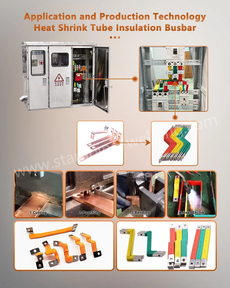
Key Technical Properties of Heat-Shrink Insulating Materials
When heat-shrink materials are used for busbar insulation in substations, they must first meet electrical insulation requirements. The materials should exhibit stable dielectric strength, volume resistivity, and voltage withstand capabilities, maintaining their insulating performance under specified operating temperatures and environmental conditions. Material thickness and insulation structures must also be determined based on system insulation coordination requirements for equipment at different voltage levels.
The heat-shrink layer must also possess excellent heat resistance. Busbars generate Joule heat during long-term operation, and load fluctuations or short-circuit faults can cause transient temperature rises; consequently, the insulating material must not only meet performance standards at ambient temperatures but also withstand continuous operating temperatures, short-term overload heating, and performance changes resulting from thermal aging.
Flame retardancy is another critical performance indicator for heat-shrink materials used in substations. Insulation materials within indoor switchgear and power distribution equipment generally require specific flame-retardant and self-extinguishing capabilities to mitigate the risk of flame propagation during abnormal heating or electrical faults. Consequently, material formulations, flame-retardancy ratings, and actual operating environments must be aligned with equipment design specifications.
Furthermore, long-term operational reliability is closely linked to a material's resistance to aging. Prolonged exposure to thermal, electric field, humidity, and mechanical stresses can alter the shrinkage stability, dielectric properties, and interfacial bonding integrity of heat-shrink materials. Therefore, material selection should not rely solely on initial insulation parameters but must also account for long-term thermal aging, environmental aging, and electrical endurance.
Relationship Between Heat-Shrink Materials and Busbar Temperature Rise
A key consideration in busbar insulation is whether the addition of an insulation layer impedes heat dissipation from the conductor. Busbar temperature rise during operation is influenced by factors such as load current, conductor cross-sectional area, contact resistance, ambient airflow, and equipment configuration; thus, the insulation design must be coordinated with the busbar's current-carrying capacity and heat dissipation conditions.
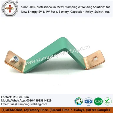
For PVC-insulated copper busbar configurations, heat conduction paths must be evaluated based on the copper bar's cross-sectional area, insulation thickness, operating current, and internal equipment space. Excessive insulation thickness can alter surface heat dissipation characteristics, whereas appropriate material thickness and structural design can satisfy insulation requirements while keeping temperature rise within acceptable limits.
During engineering design, temperature rise tests or thermal analyses should be conducted to verify that the insulated busbar operates within permissible temperature limits; the thermal performance of the entire busbar system cannot be judged solely by the material's temperature rating. Factors such as busbar arrangement, phase-to-phase spacing, and ventilation conditions significantly influence the final temperature rise, particularly in high-current switchgear and high-density distribution equipment.
Role of Heat-Shrink Insulation in Substation Operational Safety
Exposed busbars and connection points in substations are vulnerable to interference from small animals, foreign metallic objects, or accidental contact with tools. If a foreign object bridges energized conductors, it can create a short-circuit path, triggering protective system actions. Applying insulation coatings to reduce the exposed surface area of conductors minimizes the risk of direct contact between external foreign objects and live parts.
For compact switchgear, insulation treatment also facilitates the optimization of internal structures. Provided that insulation coordination requirements are met, using configurations such as PVC-insulated busbars allows for continuous protection of bare busbars; this enables designers to re-evaluate phase-to-phase clearance, phase-to-ground clearance, and equipment space utilization from the perspective of the overall insulation system.
Environmental pollution is another critical factor affecting the insulation levels of substations. The accumulation of industrial dust, salt spray, moisture, and other contaminants on insulation surfaces can create conductive paths under humid conditions, thereby increasing the risk of pollution flashover. While heat-shrink insulation layers can reduce the direct deposition of contaminants on bare conductor surfaces, effective anti-pollution design requires a comprehensive assessment that considers insulator structure, creepage distance, environmental pollution levels, and equipment operating conditions.
In coastal regions, chlorides in salt spray accelerate metal surface corrosion and can degrade the electrical performance of insulation surfaces. For such applications, environmentally resistant insulation materials should be used in conjunction with sealing structures to minimize the ingress of salt spray and moisture into critical interfaces.
Insulation Protection Against Condensation, Ice Accretion, and Low Temperatures
Condensation in high-humidity environments is a key concern for substation insulation systems. When the surface temperature of equipment falls below the dew point of the surrounding air, moisture may condense on conductor or insulation surfaces. If conductors are exposed or insulation structures have defects, condensation can form localized conductive paths.
Although heat-shrink materials cover live conductors and reduce direct moisture contact, they cannot replace a comprehensive anti-condensation design for the substation. Practical engineering solutions must manage condensation risks through a combination of equipment ventilation, heating and dehumidification, sealing measures, and insulation structure design.
In cold regions, ice accretion alters the electric field distribution on insulator surfaces and can reduce the effective creepage distance. If the ice layer contains contaminants, its electrical conductivity may increase further. For such scenarios, the risk of discharge under icing conditions can be mitigated by increasing the effective creepage distance, optimizing the insulation surface profile, and improving the conductor's protective structure.
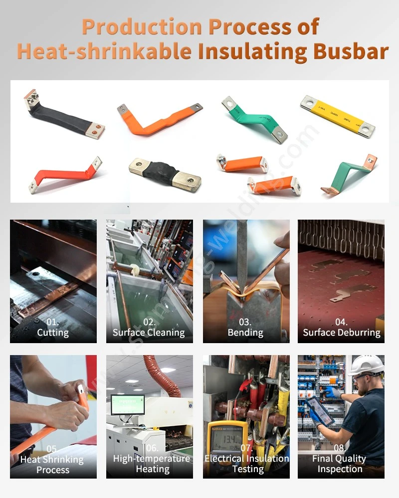
Installation and Quality Control of Heat-Shrink Busbar Insulation
The insulation performance of heat-shrink materials depends not only on the material itself but also heavily on the installation process.
Before installation, the busbar surface must be inspected for burrs, sharp corners, oil, and oxides, and cleaned or edge-treated according to product specifications. Sharp edges can cause mechanical damage to the insulation layer during the shrinking process or lead to localized electric field concentration; therefore, busbar edges typically require appropriate chamfering or rounding.
Heating temperature and uniformity must be controlled during installation. Localized overheating can damage the material surface, while insufficient heating may result in incomplete shrinkage, leaving gaps between the insulation layer and the busbar. For long busbars, heating should proceed gradually in the prescribed direction to ensure a uniform shrinking process.
Connection points are critical areas for insulation protection. Bolted connections, overlap joints, and busbar bends are prone to geometric irregularities; care must be taken to prevent wrinkling, damage, or localized stress concentration in the insulation layer. Where necessary, specialized sealing or localized insulation structures can be employed to enhance protection in these connection areas.
For equipment intended for long-term operation, post-installation procedures should include visual inspections, dimensional verification, and electrical performance testing. High-voltage equipment must undergo withstand voltage tests, insulation resistance measurements, and other necessary tests in accordance with relevant standards and project technical specifications.
Application of Heat-Shrink Materials in Various Electrical Equipment
Heat-shrink insulation technology applies not only to busbars in traditional substations but also to distribution cabinets, switchgear, transformer connection systems, cable accessories, and electrical equipment for new energy systems. Insulation materials must be specifically designed for each application based on factors such as operating voltage, operating temperature, environmental conditions, and mechanical installation methods.
In new energy battery systems, busbars often carry high DC currents and must facilitate reliable electrical connections within limited spaces. Therefore, an insulated copper busbar utilizing heat-shrink tubing can simultaneously meet the requirements for electrical connectivity and protection against electric shock through the combination of a conductor and an insulating layer.
Within battery modules and packs, the insulation structure must also accommodate vibration, thermal cycling, and spatial constraints. For certain battery interconnection systems, the EV battery connectors and the busbar insulation structure must be matched holistically to ensure coordination among connection interfaces, insulation clearances, and mechanical fixation.
In energy storage systems and the high-voltage power distribution architectures of new energy vehicles, busbar insulation materials face higher DC voltages and more complex thermal environments. Consequently, factors such as dielectric strength, flame retardancy, heat resistance, aging resistance, and dimensional stability must be incorporated into the design evaluation.
For structures utilizing heat-shrink protection, heat-shrink tubing can minimize exposed conductor areas and form a continuous insulating layer conforming to the busbar's shape. Where localized repair or protection of specific structural features is required, heat-shrink sleeves are better suited for insulating connection terminals, corners, and localized exposed areas.
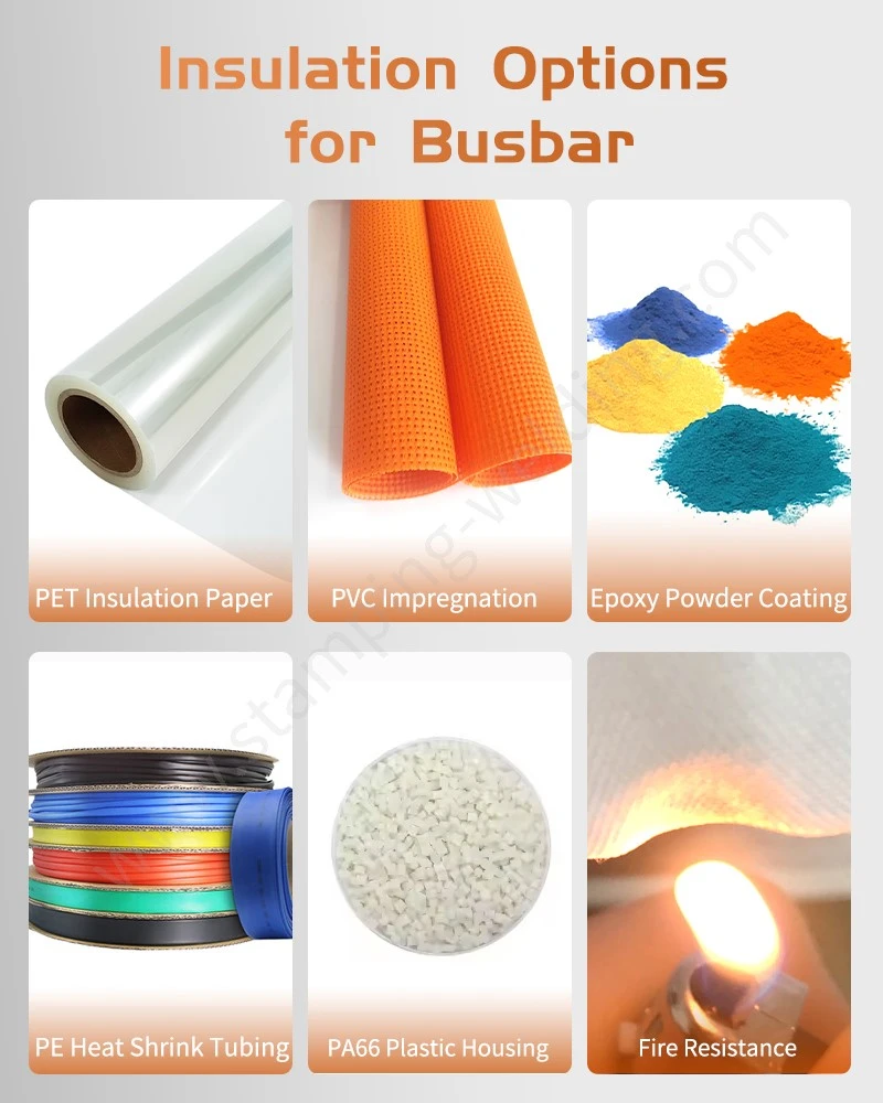
Trends in Insulation Material Selection
As substations evolve toward higher voltages, greater capacities, compact designs, and intelligent operation, performance requirements for insulation materials are steadily rising. Future heat-shrink insulation materials must simultaneously deliver higher dielectric strength, superior resistance to thermal aging, more stable mechanical properties, and reduced environmental impact.
Regarding material design, high-performance polymers, flame-retardant systems, and cross-linking technologies will continue to shape the overall performance of heat-shrink materials. For equipment intended for long-term operation, materials must not only exhibit excellent initial properties but also undergo validation against conditions such as thermal aging, damp heat, voltage stress, and mechanical durability.
In terms of structural design, the approach to insulation materials is shifting from simple "covering and protection" toward systematic insulation design. Factors such as busbar dimensions, insulation thickness, electric field distribution, creepage distance, heat dissipation paths, and installation processes must be considered concurrently.
For high-density equipment, the quality of the interface between the insulation material and the conductor will also emerge as a critical factor influencing long-term reliability. For battery and energy storage systems, the insulation design of high-current connection structures-such as battery terminal busbars-will increasingly prioritize balancing space utilization, electric shock protection, and thermal management. Meanwhile, established insulation solutions like PVC heat-shrinkable busbar sleeves will continue to demonstrate strong practical utility in power distribution and electrical connections for new energy applications.
Overall, heat-shrinkable insulation materials provide multi-layered insulation protection for electrical equipment in substations and new energy systems through methods such as continuous encapsulation, localized sealing, and creepage distance optimization. Their actual performance depends on the integrated compatibility of material properties, structural design, installation quality, and the operating environment.
When procuring materials for engineering projects, specific insulation materials and structural solutions should be selected based on factors such as voltage rating, busbar specifications, operating temperature, flame retardancy, environmental conditions, and installation methods.
contact us