Diffusion Welding Process For Copper Foil Flexible Connectors And Nickel Sheets: Key Technologies And Quality Control For Dissimilar Metal Joining
Oct 01, 2026
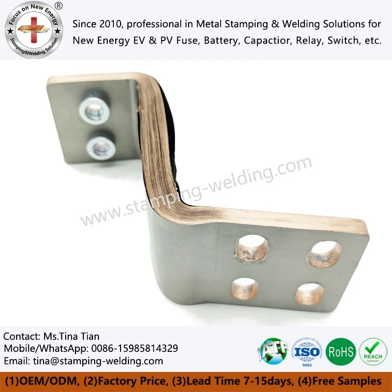
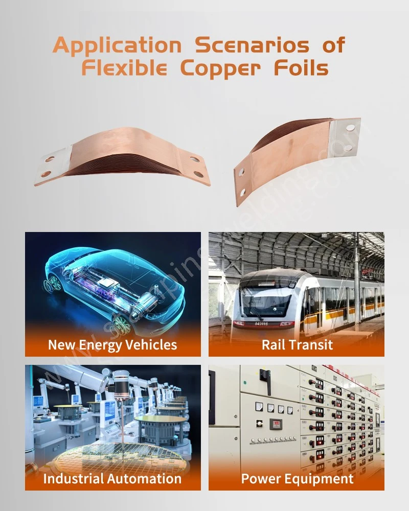
With the development of new energy vehicles, energy storage batteries, power electronics, and high-current power distribution systems, requirements for flexible conductive connectors regarding current-carrying capacity, connection reliability, mechanical flexibility, and long-term stability are constantly rising. Formed by stacking multiple layers of thin copper foil, flexible copper foil connectors offer excellent electrical conductivity and flexibility, allowing them to accommodate vibrations, displacements, and thermal expansion or contraction during equipment operation; consequently, they are widely used in battery modules, inverters, electrical connections, and high-current circuits.
In the electrical systems of new energy vehicles, flexible copper busbars for power distribution often need to simultaneously meet requirements for high current-carrying capacity and spatial adaptability. Compared to rigid copper busbars, flexible copper foil connectors can absorb some of the mechanical stress generated during assembly and operation through bending and deformation. When the connection structure also involves integration with nickel sheets, the reliability of the welding interface becomes a critical factor influencing the performance of the entire conductive assembly.
Copper and nickel are classic examples of dissimilar metals. Copper possesses high thermal conductivity and good ductility, whereas nickel exhibits high hardness, corrosion resistance, and oxidation resistance; the two materials differ significantly in terms of thermal conduction, thermal expansion, surface characteristics, and plastic deformation behavior. Improper control of temperature, pressure, duration, or interface conditions during welding can lead to issues such as inadequate bonding, increased interface resistance, localized delamination, and overheating during long-term operation.
Key Technical Challenges in Joining Dissimilar Copper and Nickel Metals
Flexible copper foil connectors typically consist of multiple layers of thin copper foil, characterized by low individual material thickness and a high number of layers. If the copper foils are misaligned, have warped edges, or contain trapped air between layers prior to welding, localized voids may form during the subsequent application of pressure and heat treatment. Failure to effectively eliminate these voids can result in poor internal bonding, causing current to concentrate in specific localized areas.
Copper conducts heat rapidly, whereas nickel possesses different thermal conduction characteristics. Under identical heat input conditions, the time required for each material to reach the state optimal for bonding differs. Therefore, copper-nickel connections cannot simply be configured using welding parameters intended for a single metal; instead, the process must be tailored to factors such as material thickness, the number of stacked layers, contact area, and product structure.
The oxide film on the nickel sheet surface is another critical factor affecting interfacial bonding. Oxide layers, along with contaminants like oil and dust, create an additional barrier at the interface, thereby reducing the actual metal-to-metal contact area. For connections required to carry high currents over the long term, such minute interfacial defects can lead to fluctuations in contact resistance and localized temperature rises.
In new energy vehicle and energy storage battery systems, these types of connections must also withstand operating conditions such as continuous vibration, thermal cycling, and frequent charge-discharge cycles. Consequently, the connection interface requires not only excellent initial electrical conductivity but also sufficient mechanical bond strength and long-term stability.
Application Characteristics of Copper Foil Flexible Connections and Laminated Structures
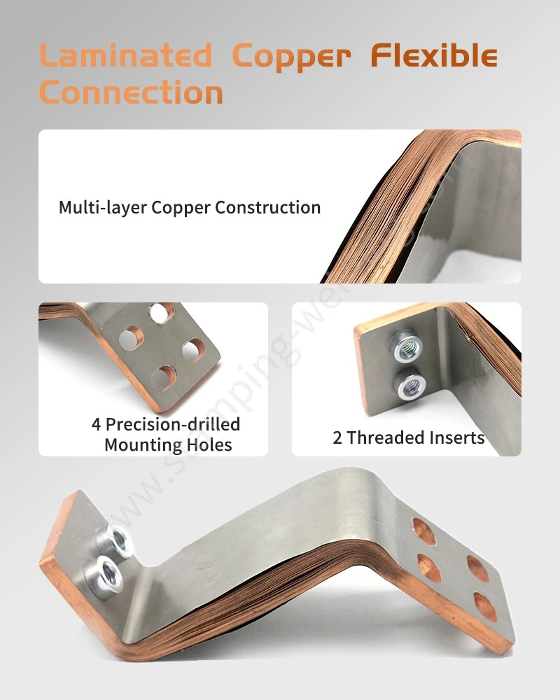
In high-current applications, laminated copper foil flexible busbars typically employ a multi-layer stack design; this increases the effective conductive cross-sectional area to meet current-carrying requirements while utilizing the inherent flexibility of the copper foil to absorb mechanical displacement.
Compared to traditional solid conductors, multi-layer structures can be customized based on available space, rated current, and connection orientation. For applications with compact internal battery pack layouts, flexible copper foil busbars can be adapted to various mounting positions through pre-determined bending directions and terminal configurations, thereby mitigating the spatial constraints often imposed by rigid connectors.
Another characteristic of laminated copper foil structures is their compatibility with various terminal materials. For instance, while the copper foil body handles the primary current-carrying function, nickel sheets can serve as auxiliary materials at specific interfaces to meet welding, connection, or environmental resistance requirements. Depending on the specific application, options such as bare copper, plated copper, or other surface treatments can be selected to suit actual needs.
In certain high-current electrical equipment, multi-layer flexible copper foil busbars effectively balance electrical conductivity with mechanical flexibility, making them particularly suitable for connection zones that require the absorption of installation tolerances and operational vibrations.
Fundamental Principles of Diffusion Bonding for Copper-Nickel Joints
Copper-nickel diffusion bonding is a solid-state joining technique. Its fundamental principle involves bringing the metal surfaces to be joined into intimate contact under specific temperature and pressure conditions, thereby forming a stable metallurgical bond through atomic-scale interdiffusion. Unlike traditional welding methods that rely on significant amounts of molten metal to form a joint, properly controlled diffusion bonding minimizes the formation of distinct melt zones and reduces welding-induced deformation.
For assemblies combining copper foil and nickel sheets, the process focus is not merely on raising the temperature, but on establishing a stable window of temperature, pressure, and holding time to allow for gradual interface mating and diffusion.
In practical applications-such as flexible copper foil busbars with laminated copper shunts-the design must balance flexible sections with rigid connection zones. Consequently, the compression parameters at the connection ends cannot simply be set based on the bulk copper foil structure. The ends require sufficient bond strength while avoiding excessive compression that could cause localized hardening of the copper foil.
Pre-welding Cleaning and Material Pre-treatment
Surface treatment prior to welding is a critical step in ensuring the quality of copper-nickel joints. Surfaces of the copper foil and nickel sheets must be free of oil, fingerprints, dust, processing residues, and significant oxidation to ensure the cleanliness of the bonding areas.
For multi-layer copper foil structures, it is also essential to inspect for foreign matter between layers and ensure the ends are flat. If contaminants exist between layers, subsequent pressure application cannot fully eliminate their impact, potentially leading to localized discontinuities.
For structures such as laminated copper foil connectors, dimensional consistency at the ends is particularly important. End width, stacking alignment, and the coverage area of the nickel sheets must remain consistent to ensure uniform pressure distribution across the entire joint area.
Stacking and Fixture Positioning
Following surface pre-treatment, the copper foil layers and end configurations must be arranged according to product design specifications. The edges of the copper foil should be aligned, avoiding layer misalignment, loose strands, creases, or significant edge curling.
Nickel sheets are typically positioned to cover the ends of the copper foil as specified in the design and are secured using fixtures. These fixtures determine the product's final shape and directly influence pressure distribution. Misalignment during positioning can result in insufficient local pressure, preventing adequate contact in certain areas.
For products requiring specific spatial configurations-such as flexible-shaped copper busbars used for line busbars-tooling design must account for the relationship between formed dimensions and welding zones to prevent subsequent bending areas from being adversely affected by excessive heat and pressure.
Pre-compression, Air Evacuation, and Interface Leveling
Applying appropriate pre-compression before the actual heating phase allows the multiple layers of copper foil to gradually conform to one another while expelling air trapped between layers. For thin copper foil laminates, the pre-compression process should not be overly aggressive; otherwise, it may cause localized foil deformation or trap air pockets inside.
A well-designed pre-compression process ensures the gradual formation of a stable contact interface and minimizes microscopic gaps. Pressure uniformity is particularly critical for large-area connections, as the actual contact state across different zones directly influences subsequent heat conduction and atomic diffusion processes.
Isothermal Diffusion and Pressure Control
Following pre-compression, the process enters the isothermal diffusion stage. This phase requires maintaining stable temperature and pressure to ensure continuous, intimate contact at the copper-nickel interface.
If the temperature is too low, atomic diffusion is insufficient, and the interface bond strength may fail to meet requirements. Conversely, excessively high temperatures or prolonged holding times can alter the copper foil's microstructure, cause localized softening, or even compromise the performance of flexible sections. Therefore, process parameters must be validated based on material grade, copper foil thickness, number of layers, and connection area.
For power electronics applications-such as laminated copper busbars for inverters-the resistance stability of the connection interface is paramount. Inverters typically operate at high current densities; if localized resistance increases within the connection zone, it can create an additional heat source, potentially damaging surrounding insulation materials and structural components.
Controlled Cooling Under Pressure and Stress Management
Copper and nickel exhibit different thermal expansion behaviors; consequently, rapid pressure release and cooling immediately after diffusion welding are unsuitable. If the temperature drops rapidly while pressure is simultaneously released, the materials' differing contraction rates can generate significant residual stress at the connection interface.
Controlled cooling under pressure helps mitigate this transient stress, allowing the connection structure to stabilize gradually. This step is particularly critical for flexible interconnect products requiring subsequent bending, as excessive residual stress can cause the connection ends to harden or even lead to cracking during subsequent mechanical movement.
Principles for Controlling Key Process Parameters
Temperature control must balance material diffusion with microstructural stability. Insufficient temperature may result in inadequate bonding, while excessive heat input can alter the mechanical properties of the copper foil. Therefore, the optimal process window should be established through sample tensile testing, peel tests, resistance measurements, and cross-sectional analysis.
Pressure control must account for copper foil thickness and the number of layers. Insufficient pressure leads to poor interfacial contact, whereas excessive pressure can damage the copper foil, causing the flexible zone to lose its original bending capability.
Dwell time determines the extent of interfacial diffusion. Since copper and nickel are dissimilar metals, the actual time required depends heavily on material condition, bonding area, and temperature. Welding quality should not be judged solely by equipment settings; instead, the process window should be defined based on actual inspection results.
Impact of Graphite Tooling on Batch Consistency
During diffusion welding, the flatness, parallelism, and thermal stability of the tooling directly affect product quality. Surface irregularities, scratches, or carbon buildup on the graphite tooling can cause localized pressure concentrations, leading to thickness variations or uneven bonding in the connection area.
Tooling contact surfaces must be cleaned prior to production, and flatness and parallelism should be checked regularly. For continuous mass production, dimensional stability under prolonged thermal exposure is also critical to prevent variations in pressure and temperature conditions across different batches caused by heat accumulation.
For custom products-such as flexible copper foil laminated busbars-tooling must be matched to the product's length, width, layer count, and terminal configuration; thus, tooling design itself is a vital factor in ensuring batch consistency.
Common Quality Issues and Root Cause Analysis
Issues such as nickel sheet peeling, delamination, or insufficient pull-off strength are typically associated with inadequate removal of surface oxides, interfacial contamination, insufficient temperature, or insufficient diffusion time. These issues should be systematically addressed through surface treatment, precise tooling positioning, and parameter verification during production. Significant hardening and reduced flexibility at the copper foil ends may be attributed to excessive heat input, prolonged holding times, or excessive pressure. For flexible interconnect products, particular attention should be paid to the heat-affected zone between the welded area and the flexible section.
Internal voids or delamination between copper foil layers are typically caused by misaligned stacking, insufficient pre-compression, or excessively rapid heating. Proper stacking and effective pre-compression with air evacuation can minimize these internal defects.
If abnormal temperature rise or high connection resistance occurs during operation, the interface should be inspected for issues such as micro-voids, oxide inclusions, or inadequate diffusion bonding. For high-current interconnects, it is recommended to combine resistance measurements with temperature rise testing, rather than relying solely on visual inspection to assess connection quality.
During mass production, significant fluctuations in product quality necessitate a review of tooling temperature, cleanliness, positioning accuracy, and equipment parameter stability. Process parameters should not be simply replicated across different product specifications; instead, they should be re-validated based on specific materials and structural designs.
Quality Evaluation System for Copper Foil Flexible Interconnects
Quality evaluation of copper foil flexible interconnects should extend beyond visual inspection of the weld to encompass mechanical, electrical, and environmental adaptability. Mechanical performance can be assessed through tensile, peel, and bending tests to evaluate the bond strength of the connection zone.
Electrical performance can be verified by measuring DC resistance, temperature rise under load, and long-term current-carrying stability. Environmental reliability can be assessed through tests such as thermal cycling, vibration, and damp-heat exposure, tailored to actual application conditions.
In applications such as new energy vehicles and energy storage systems, high-power interconnect structures-such as copper laminated busbars-require consideration of the impact of long-term thermal cycling on interface stability. As equipment undergoes repeated cycles of heating during operation and cooling during downtime, thermal stresses at the connection interface fluctuate; consequently, initial weld strength is not a definitive indicator of long-term reliability.
For interconnect structures requiring high flexibility, parameters such as bend radius, number of bending cycles, and resistance changes post-bending should also be verified. Establishing correlations between mechanical performance, electrical performance, and environmental reliability enables a more accurate assessment of whether the product meets the requirements of actual operating conditions.
Evolution of Copper-Nickel Flexible Connection Technology
As new energy vehicles, energy storage systems, and power electronics evolve toward higher voltages, currents, and power densities, flexible conductive connectors are transforming from simple conductive components into integrated connection structures that address electrical, mechanical, and thermal management needs.
In battery systems for new energy vehicles, copper foil busbars designed for high-current, high-voltage applications must handle substantial currents within confined spaces while withstanding the vibrations and temperature fluctuations inherent in vehicle operation. Consequently, factors such as material thickness, lamination structure, terminal welding, and the design of bending zones require a holistic, coordinated approach.
For equipment such as battery modules, energy storage converters, and inverters, laminated flexible busbars utilize a layered conductor structure to shorten connection paths, while their flexibility allows them to accommodate assembly tolerances and mechanical stresses.
Internally, laminated connectors for electrical equipment can be customized to fit specific spatial constraints and connection orientations, resulting in more compact conductive structures and alleviating the installation space limitations often associated with traditional rigid connectors.
Future development of copper foil flexible connections will focus on high current-carrying capacity, lightweighting, low electrical resistance, flexible structural design, and automated manufacturing. As mass production of new energy vehicles and energy storage equipment scales up, there will be increasingly stringent requirements regarding connector consistency, traceability, and long-term reliability.
From an engineering design perspective, joining dissimilar metals-such as copper and nickel-involves more than optimizing welding parameters; it results from the interplay of material selection, surface treatment, lamination design, pressure control, thermal management, tooling precision, and reliability validation. A stable manufacturing window for copper foil flexible connections can only be established by aligning materials and process conditions with actual requirements for current, temperature, vibration, and spatial constraints.
For engineering projects requiring customized copper foil flexible connections, laminated busbars, or high-current flexible connectors, the procurement phase should prioritize confirming material specifications, current-carrying requirements, terminal connection methods, dimensional tolerances, bending specifications, and reliability testing criteria. Complete engineering alignment before mass production.
contact us