Arc Quenching Ceramic Chute Plates and Barriers for 1500V DC High-Speed Circuit Breakers and Fuses
Nov 09, 2026
Arc-chute ceramic plates and barriers in 1500V DC switching devices must withstand rapid thermal loading, arc plasma exposure, metal-vapor deposition, and repeated electrical interruption without cracking or developing conductive surface paths. Material selection, slot geometry, dimensional accuracy and surface condition directly affect insulation integrity and arc chamber performance. Cordierite-mullite composites and high-alumina ceramics are candidate materials for these components, but their suitability must be validated against the actual arc energy, interruption sequence, and dielectric requirements of the device.
Why 1500V DC Arc Interruption Requires High-Temperature Ceramic Barriers
Unlike AC systems, DC circuits do not provide a natural current zero crossing every half-cycle. When a DC circuit breaker or fuse opens under load, the arc may continue conducting until the interruption mechanism increases arc voltage and removes sufficient energy from the circuit.
At 1500V DC, the arc chamber must manage several simultaneous physical effects:
High-temperature plasma exposure.
Rapid local heating and cooling.
Metal-vapor generation from contact and conductor erosion.
Gas pressure changes inside the arc chamber.
Surface contamination and conductive deposition.
Electrical stress across narrow ceramic barriers and slots.
Ceramic chute plates and insulating barriers help define the arc chamber geometry, separate conductive components, and maintain electrical insulation between adjacent regions. Their performance depends on both intrinsic material properties and the geometry of the complete interruption assembly.
DC arc behavior and ceramic thermal loading
During interruption, an arc transfers energy to nearby surfaces through plasma radiation, convection, and direct interaction with the arc root. The local ceramic temperature can rise much faster than the average temperature of the component.
This creates a thermal gradient between the exposed surface and the cooler internal material. If the gradient produces tensile stress greater than the material's fracture resistance, cracking or spalling may occur.
The main variables affecting ceramic thermal shock resistance include:
| Engineering variable | Effect on ceramic performance | Design consideration |
| Coefficient of thermal expansion | Determines thermal strain under temperature change | Lower expansion may reduce thermal stress |
| Thermal conductivity | Influences heat distribution through the component | Evaluate against local heating rate |
| Elastic modulus | Affects stress generated by constrained thermal expansion | Consider material and geometry together |
| Fracture toughness | Influences resistance to crack propagation | Validate using appropriate mechanical tests |
| Porosity | Affects strength, thermal behavior, and surface condition | Control density and pore distribution |
| Wall thickness | Influences thermal gradients and mechanical strength | Avoid unnecessarily thick sections |
| Slot geometry | Changes local stress concentration and arc path | Use controlled radii and consistent dimensions |
A nominal plasma temperature should not be treated as the actual ceramic surface temperature. Arc temperature, exposure duration, heat flux, and component temperature are different quantities. Qualification should reproduce the device's specified interruption conditions rather than rely on a generic temperature claim.
Failure modes in 1500V DC ceramic arc barriers
| Failure mode | Primary cause | Potential consequence | Recommended verification |
| Thermal cracking | Rapid temperature gradient | Loss of structural integrity | Thermal shock testing |
| Edge chipping | Mechanical impact or stress concentration | Reduced insulation distance | Visual and dimensional inspection |
| Surface erosion | Repeated arc exposure | Change in barrier geometry | Post-interruption dimensional inspection |
| Metal-vapor deposition | Contact and conductor erosion | Surface contamination | Post-test surface examination |
| Conductive tracking | Contaminated surface under electrical stress | Reduced insulation resistance | Dielectric and insulation resistance tests |
| Slot deformation | Manufacturing or thermal damage | Incorrect arc chamber geometry | Optical or CMM inspection |
| Internal porosity | Inconsistent ceramic forming or firing | Reduced mechanical reliability | Density and section inspection |
The ceramic component must therefore be evaluated as part of the complete arc chamber. Material properties alone cannot establish interruption capability.
Cordierite-Mullite Composite vs. 95% Alumina for Arc Chute Components
Material selection is one of the main design decisions for ceramic barriers used in high-voltage DC switching equipment.
Cordierite-mullite composites and high-alumina ceramics have different thermal, mechanical, and electrical characteristics. The appropriate choice depends on the balance between thermal shock resistance, mechanical loading, dielectric requirements, manufacturing geometry, and operating environment.
Cordierite-mullite composite ceramic
Cordierite-containing ceramics are commonly considered where low thermal expansion and thermal shock resistance are important. Mullite contributes to the refractory and structural characteristics of the composite.
A cordierite-mullite formulation can be engineered to balance:
Thermal expansion.
Thermal conductivity.
Mechanical strength.
Resistance to rapid temperature changes.
Dimensional stability after firing.
Manufacturing suitability for slotted or grooved structures.
The final properties depend on the raw-material ratio, particle-size distribution, forming method, firing profile, porosity, and resulting microstructure.
A ceramic formulation should not be specified only by the names of its constituent phases. The finished component must be characterized using measured physical properties and application-specific tests.
95% alumina ceramic for electrical insulation barriers
95% alumina ceramic is widely used in electrical insulation components because of its combination of dielectric strength, mechanical properties, hardness, and chemical stability.
For arc chamber applications, relevant characteristics include:
High electrical resistivity under specified conditions.
Resistance to surface erosion.
Mechanical strength for thin-wall and slotted geometries.
Dimensional stability during firing.
Compatibility with precision diamond grinding.
However, high alumina content does not automatically guarantee superior thermal shock performance. Its thermal expansion, thermal conductivity, fracture toughness, and component geometry must be considered together.
Material comparison for 1500V DC arc chute plates
| Selection factor | Cordierite-mullite composite | 95% alumina |
| Primary design consideration | Thermal shock resistance and dimensional stability | Electrical insulation and mechanical strength |
| Thermal expansion | Formulation-dependent; often selected for relatively low expansion | Generally higher than cordierite-rich formulations |
| Thermal conductivity | Depends on phase composition and porosity | Generally higher than many cordierite-rich ceramics |
| Mechanical strength | Depends strongly on mullite content and porosity | Typically suitable for structural electrical insulation |
| Hardness | Composition-dependent | High |
| Precision machining | Requires suitable ceramic grinding processes | Suitable for diamond grinding |
| Typical design focus | Rapid thermal cycling and thermal gradient management | Dielectric separation and structural insulation |
| Main qualification concern | Strength retention after thermal shock | Thermal stress and brittle fracture under rapid heating |
The comparison is qualitative. Actual values must be obtained from the selected ceramic grade's material data and verified using production samples.
Ceramic material qualification parameters
For an arc chute ceramic plate or barrier, the material specification should define measurable characteristics rather than rely on a generic grade description.
| Material characteristic | Recommended evaluation | Engineering purpose |
| Bulk density | Archimedes method or approved density test | Verify firing consistency |
| Open porosity | Standardized porosity measurement | Assess pore structure |
| Flexural strength | Three-point or four-point bending | Evaluate mechanical integrity |
| Fracture toughness | Applicable ceramic test method | Assess crack propagation resistance |
| Thermal expansion | Dilatometry | Calculate thermal strain |
| Thermal conductivity | Applicable thermal measurement method | Evaluate heat distribution |
| Dielectric strength | Standardized dielectric breakdown test | Verify electrical insulation |
| Volume resistivity | Electrical resistivity measurement | Evaluate bulk insulation |
| Thermal shock resistance | Defined heating and cooling cycle | Assess resistance to thermal gradients |
Material limits should be established from the breaker or fuse design specification. A dielectric breakdown value measured on a laboratory coupon should not be directly treated as the allowable operating field strength of a finished component.
Request Arc Chute Ceramic Material Evaluation
Precision Extrusion and Diamond Grinding for Ceramic Slot Geometry
Arc chute plates frequently contain parallel slots, channels, grooves or partitions that control the internal geometry of the arc chamber. Dimensional variation can affect plate positioning, assembly clearance and the intended arc path.
For complex multi-slot components, ceramic manufacturing generally requires a combination of forming, firing and precision finishing.
Porous-channel extrusion for multi-slot ceramic structures
Extrusion is suitable for ceramic profiles with continuous channels or repeated longitudinal features. A prepared ceramic batch is forced through a shaped die to produce the required green profile.
The process involves several controlled stages:
1. Powder preparation: Ceramic powders and additives are mixed to achieve the required forming characteristics.
2. Batch conditioning: Moisture and plasticity are adjusted to support stable extrusion.
3. Die design: The extrusion die defines the initial slot and external profile geometry.
4. Extrusion: Material passes through the die under controlled pressure and feed conditions.
5. Drying: Moisture is removed under controlled conditions to reduce deformation and cracking.
6. Debinding: Organic additives are removed according to the selected formulation.
7. Firing: The ceramic body is densified under a specified temperature profile.
8. Finishing: Critical surfaces and dimensions are corrected through grinding or other suitable machining.
Extrusion die design must account for material flow and firing shrinkage. Internal channels may deform during drying or firing if the geometry, support conditions, and process parameters are not properly balanced.
Die compensation and firing shrinkage control
The green ceramic component is larger than the final fired part because of drying and sintering shrinkage. The amount of shrinkage depends on powder characteristics, forming density, moisture distribution, and firing conditions.
For multi-slot ceramic barriers, uneven shrinkage can produce:
Slot-width variation.
Channel misalignment.
Bowing or twisting.
Uneven wall thickness.
Edge distortion.
Cracks around narrow sections.
The extrusion die should therefore be compensated using measured shrinkage data from trial production. A single theoretical shrinkage factor may be insufficient for components with different wall thicknesses or complex internal channels.
Diamond grinding for ±0.05mm dimensional control
After firing, diamond grinding can be used to finish critical ceramic dimensions. It is particularly relevant for slot widths, mounting surfaces, external profiles and reference faces.
A dimensional tolerance of ±0.05mm can be specified for selected features where the geometry, material and production process support it. This tolerance should not be applied automatically to every surface of a ceramic component.
Important grinding variables include:
Diamond wheel grit size and bond type.
Wheel speed and feed rate.
Grinding depth per pass.
Coolant supply and temperature.
Workpiece clamping method.
Edge support and corner geometry.
Wheel dressing and wear compensation.
Ceramic grinding generates localized mechanical stress. Excessive feed or poor wheel condition can cause edge chipping, subsurface cracks, and dimensional instability.
Critical dimensional characteristics for ceramic arc chute plates
| Critical characteristic | Typical manufacturing risk | Recommended inspection |
| Overall length and width | Firing shrinkage variation | CMM or optical measurement |
| Plate thickness | Non-uniform forming or grinding | Micrometer or thickness gauge |
| Slot width | Die wear or grinding variation | Optical comparator or vision measurement |
| Slot pitch | Extrusion distortion | CMM or optical measurement |
| Parallelism | Uneven firing or grinding | CMM |
| Flatness | Drying or firing deformation | Surface plate and measurement system |
| Edge condition | Grinding-induced chipping | Magnified visual inspection |
| Surface roughness | Finishing variation | Surface roughness measurement where specified |
Surface Contamination, Metal Vapor Deposition and Conductive Tracking
During circuit interruption, metal vapor can be generated by erosion of contacts, conductors and other arc-exposed components. These particles may deposit on ceramic surfaces and form localized contamination layers.
The electrical effect depends on the deposited material, surface temperature, deposit thickness, humidity, voltage stress, and creepage geometry.
A ceramic barrier that initially meets insulation requirements may experience reduced surface insulation resistance after repeated interruption cycles.
How metal-vapor deposition affects ceramic insulation
Metal vapor can condense on cooler surfaces within the arc chamber. Depending on the interruption mechanism and chamber geometry, deposits may accumulate around slots, edges, and surfaces facing the arc.
Potential consequences include:
Reduced surface insulation resistance.
Local electric-field concentration.
Increased leakage current.
Surface flashover under subsequent electrical stress.
Formation of conductive paths between adjacent regions.
Metal deposition should not be described as carbonization in every case. Conductive tracking may involve metallic deposits, carbonaceous residues, surface degradation, or a combination of these mechanisms.
Surface condition and microstructure control
Ceramic surface treatment should be selected according to the required insulation and contamination performance. It may involve controlled grinding, surface finishing, cleaning, or other application-specific treatments.
Important surface characteristics include:
| Surface characteristic | Potential influence | Inspection or validation |
| Surface roughness | Affects local contamination retention and surface condition | Roughness measurement |
| Open surface pores | May retain deposited particles | Microscopy and porosity evaluation |
| Grinding cracks | Can reduce mechanical and dielectric reliability | Magnified inspection |
| Surface contamination | Can lower insulation resistance | Cleaning verification |
| Edge chipping | May increase local electric-field concentration | Optical inspection |
| Surface deposits after interruption | May create conductive paths | Post-test microscopy and electrical testing |
A smoother surface does not automatically provide better arc resistance. Surface roughness, contamination retention, creepage distance, and local electric-field distribution must be evaluated as a system.
Electrical validation after repeated interruption cycles
The ceramic barrier should be evaluated after the specified number of switching or fuse interruption events. Testing should use the actual device configuration or a representative test fixture.
Recommended validation includes:
Visual inspection for cracks and erosion.
Dimensional measurement of critical slots and barriers.
Surface microscopy for metal-vapor deposition.
Insulation resistance measurement.
Dielectric withstand testing.
Surface tracking assessment under the specified test conditions.
The applicable acceptance limits must be defined by the end-device specification and relevant product standards. IEC 60947-2 may be relevant to low-voltage circuit-breaker applications, while IEC 60269 applies to low-voltage fuse systems. A 1500V DC product must be assessed against the applicable voltage category, product scope, and current edition rather than assuming that one standard covers every device.
Discuss Ceramic Barrier Design and Testing
Arc Chute Geometry and Ceramic Barrier Design for 1500V DC Devices
Ceramic plates are not independent arc-quenching devices. Their geometry works together with the magnetic blowout system, arc splitter arrangement, contact opening mechanism, and gas exhaust structure.
The design objective is to provide the required arc movement, separation, and insulation while maintaining sufficient mechanical integrity under thermal and pressure loading.
Slot geometry and arc chamber configuration
Arc chute slot geometry affects the available path for arc movement and the arrangement of insulating barriers. Design parameters may include:
Slot width and pitch.
Plate thickness.
Barrier spacing.
Internal channel length.
Edge radius.
Mounting and locating features.
Clearance to adjacent conductive components.
The correct values depend on the breaker or fuse architecture. Slot dimensions should be derived from the arc chamber design rather than selected using generic ceramic component dimensions.
Design considerations for ceramic barriers
| Design parameter | Engineering objective | Main verification |
| Slot width | Maintain intended internal geometry | Optical measurement |
| Plate thickness | Balance mechanical strength and assembly space | Thickness inspection |
| Barrier spacing | Maintain electrical separation | Dimensional and dielectric testing |
| Edge radius | Reduce local stress concentration | Profile measurement |
| Mounting interface | Prevent assembly interference | Fit and dimensional inspection |
| Surface condition | Limit defect-related insulation risks | Surface inspection |
| Thermal mass | Manage transient heat absorption | Thermal analysis and interruption testing |
Ceramic barrier design versus assembly-level performance
A ceramic plate may satisfy its individual material and dimensional specifications while the complete arc chamber still fails interruption testing.
Potential system-level issues include:
Incorrect plate spacing.
Misalignment between adjacent slots.
Inadequate exhaust flow.
Unintended conductive bridging.
Contact erosion outside the expected region.
Localized thermal concentration.
Insufficient clearance between conductive components.
For this reason, ceramic component qualification should include assembly fit verification and, where possible, evaluation in a representative arc chamber.
Quality Control and Qualification for Industrial Arc Chute Ceramics
A ceramic arc chute component requires process control from raw-material preparation through final inspection. Because ceramic firing is irreversible and dimensional shrinkage occurs during production, inspection should be distributed across forming, drying, firing, and finishing stages.
Manufacturing quality control plan
| Production stage | Key control item | Typical inspection method | Defect prevented |
| Raw-material preparation | Powder composition and batch identity | Material certificate and batch records | Material variation |
| Mixing and conditioning | Moisture and forming consistency | Process parameter monitoring | Extrusion instability |
| Die extrusion | Profile and channel geometry | Optical inspection | Slot deformation |
| Drying | Moisture removal and dimensional stability | Process monitoring and visual checks | Drying cracks |
| Debinding and firing | Temperature profile and shrinkage | Furnace records and sample measurement | Cracking and distortion |
| Diamond grinding | Slot dimensions and surface condition | Optical measurement and CMM | Dimensional deviation |
| Final cleaning | Residual particles and contamination | Visual inspection | Surface contamination |
| Final inspection | Critical dimensions and physical properties | Drawing-based inspection plan | Nonconforming delivery |
Dimensional inspection and CMM verification
CMM inspection is suitable for verifying external dimensions, mounting features, and selected geometric relationships. Narrow slots and small internal features may require optical measurement systems or dedicated gauges, depending on probe access and measurement uncertainty.
A complete inspection report should identify:
Part number and drawing revision.
Measurement equipment and calibration status.
Datum alignment.
Nominal dimensions and tolerances.
Actual measured values.
Measurement uncertainty where required.
Inspection quantity and sampling plan.
For ceramic components with a specified ±0.05mm tolerance, the measurement system should have sufficient capability to distinguish acceptable parts from those near the tolerance limits.
Recommended material and functional validation
| Validation item | Purpose | Typical evaluation |
| Density | Verify ceramic consolidation | Bulk density measurement |
| Flexural strength | Assess mechanical integrity | Ceramic bending test |
| Thermal expansion | Evaluate thermal strain | Dilatometry |
| Thermal shock | Assess resistance to rapid temperature changes | Defined thermal cycling |
| Dielectric strength | Verify bulk insulation | Dielectric breakdown test |
| Insulation resistance | Evaluate electrical insulation | Specified voltage and environment |
| Surface condition | Detect cracks, pores, and grinding defects | Optical microscopy |
| Arc exposure | Assess component behavior under interruption | Representative device-level testing |
Traceability and customer quality documentation
For automotive, ESS, and PV switching-device supply chains, the quality package should be aligned with the customer's drawing and validation requirements.
Where requested, documentation may include:
Raw-material certificates.
Ceramic formulation and batch identification.
Process flow and inspection plan.
Furnace temperature records.
Dimensional inspection reports.
Physical property test results.
Nonconformance and corrective-action records.
PPAP documentation where applicable.
IATF 16949 and ISO 14001 should only be claimed when the relevant manufacturing entity and site are covered by valid certification. Product-specific performance claims must be supported by test data.
Custom Ceramic Tooling and OEM Manufacturing for Arc Chute Plates
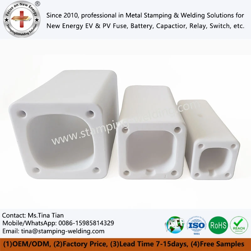
Custom ceramic arc chute plates often require dedicated extrusion dies, firing compensation, and precision grinding fixtures. Tooling design should be based on the finished component drawing, material formulation, and expected production volume.
Information required for ceramic DFM evaluation
| Required input | Engineering purpose |
| 2D drawing and 3D model | Define final geometry and tolerances |
| Ceramic material specification | Establish formulation and property targets |
| Slot width and pitch | Determine extrusion die and grinding requirements |
| Wall thickness | Evaluate forming and firing risks |
| Dimensional tolerance | Define finishing and inspection methods |
| Operating voltage | Establish electrical insulation requirements |
| Interruption current and test conditions | Define application-level qualification |
| Thermal exposure profile | Evaluate thermal shock requirements |
| Annual production volume | Determine tooling and process investment |
| Assembly interface | Verify fit with the arc chamber |
Tooling development and mass-production controls
A typical development sequence includes:
1. Drawing and material specification review.
2. Ceramic formulation and manufacturing feasibility assessment.
3. Extrusion die or forming-tool design.
4. Trial forming and firing.
5. Shrinkage measurement and die compensation.
6. Diamond grinding process development.
7. First-article dimensional inspection.
8. Material property and functional validation.
9. Production approval and batch control.
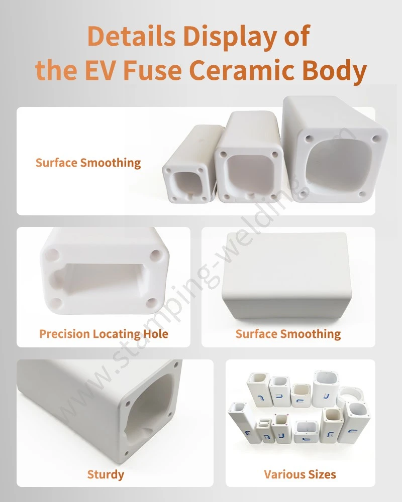
The first-article inspection should focus on slot geometry, wall thickness, flatness, edge condition, and mounting interfaces. For high-voltage switching applications, the customer's functional test requirements should be confirmed before production release.
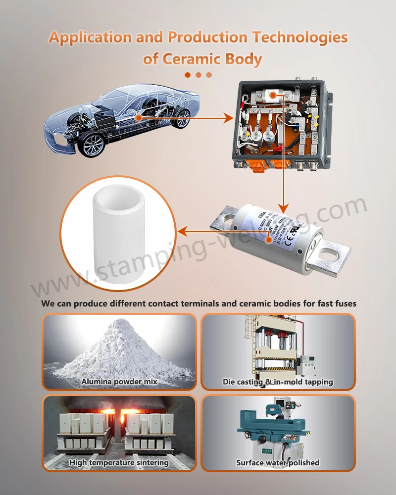
Apollo can evaluate custom industrial ceramic tube and plate tooling requirements for electrical fuse and arc chamber applications. Final production feasibility depends on component geometry, material specification, tolerance, and required validation scope.
FAQ: 1500V DC Arc Chute Ceramic Plates and Barriers
1. Which ceramic material is suitable for 1500V DC arc chute plates: cordierite-mullite or 95% alumina?
Both are potential candidates. Cordierite-mullite may be selected for thermal shock considerations, while 95% alumina is commonly considered for electrical insulation and mechanical strength. Final selection requires application-specific thermal, dielectric, and interruption testing.
2. Can ceramic arc chute plates be manufactured with ±0.05mm slot tolerances?
Yes, selected slot dimensions can be finished to ±0.05mm using precision diamond grinding, provided the component geometry and production process support the tolerance. Inspection should use calibrated optical measurement or suitable CMM methods.
3. How can conductive metal-vapor deposits on ceramic barriers be evaluated after DC interruption?
Inspect the exposed surfaces using microscopy, then perform specified insulation resistance and dielectric withstand tests. Representative interruption testing is needed to evaluate contamination and tracking under actual device conditions.
contact us