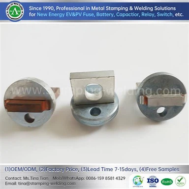
Moving and Stationary Copper Contacts for HVDC Relays: Silver Alloy Brazing & Arc Resistance
Nov 02, 2026
Moving and stationary copper contacts in 800V high-voltage DC relays must maintain low electrical resistance while withstanding arc erosion, contact welding, and repeated mechanical impact. A typical contact assembly combines a TU1 oxygen-free copper conductive arm with an AgSnO₂ or AgNi contact tip, joined through a controlled silver-alloy brazing process. Material selection, braze integrity, contact geometry, and opening dynamics must be evaluated together to achieve stable switching performance over the specified electrical and mechanical life.

800V HVDC Relay Contact Engineering: Arc Erosion and Contact Failure
High-voltage DC relays are used in electric vehicle battery disconnect units (BDUs), power distribution systems, and energy storage circuits. Unlike AC switching, DC has no natural periodic zero-crossing point. Once an arc forms between separating contacts, the relay must extinguish it through its electromagnetic, mechanical, and arc-chamber design.
The moving and stationary copper contacts are therefore exposed to combined electrical, thermal and mechanical loading.
Why 800V DC interruption accelerates contact degradation
When the moving contact separates from the stationary contact under load, current may continue flowing through an ionized plasma channel. The arc temperature can locally melt or vaporize contact material, causing material transfer, surface cratering, and erosion.
The severity of contact damage depends on several electrical and mechanical conditions:
Circuit voltage: Higher DC voltage increases the challenge of arc extinction and dielectric recovery.
Interruption current: Higher current increases arc energy and thermal loading.
Circuit inductance: Stored magnetic energy can sustain current after contact separation.
Opening velocity: Contact separation speed influences arc duration and contact gap development.
Contact geometry: Contact diameter, thickness, and surface profile affect current density and arc-root movement.
Contact force: Insufficient closed-contact force can increase constriction resistance and local heating.
Arc management: Magnetic blowout, gas pressure, arc runners, and chamber geometry influence arc movement and extinction.
This relationship explains why contact material cannot be evaluated independently of the relay's electrical interruption conditions. Two contact materials tested at different current, voltage, or inductance conditions cannot be compared reliably.
Common failure modes in moving and stationary contacts
| Failure mode | Physical mechanism | Potential consequence | Relevant control |
| Arc erosion | Local melting and material vaporization | Contact mass loss and surface damage | Contact alloy selection and arc-system design |
| Material transfer | Directional movement of molten contact material | Uneven contact surfaces | Polarity-specific switching evaluation |
| Contact welding | Local melting followed by solidification under contact pressure | Failure to open | Anti-welding material and force optimization |
| Contact resistance increase | Surface oxidation, erosion, or reduced real contact area | Excessive temperature rise | Contact resistance monitoring |
| Contact bounce | Repeated impact and separation after closure | Electrical arcing and unstable switching | Spring design and moving assembly dynamics |
| Braze failure | Thermal stress or inadequate joint integrity | Increased resistance or contact separation | Brazing process validation |
| Copper-arm deformation | Repeated impact or excessive thermal loading | Misalignment and unstable contact pressure | Mechanical design and fatigue validation |
Moving versus stationary contact design
The two contact positions do not necessarily experience identical operating conditions.
| Design factor | Moving copper contact | Stationary copper contact |
| Mechanical loading | Repeated impact and acceleration | Primarily receives impact from moving assembly |
| Contact bounce | Directly influenced by moving mass and spring dynamics | Influences rebound at the interface |
| Electrical loading | Carries current through a moving conductive path | Carries current through a fixed conductive path |
| Assembly requirements | Must maintain alignment throughout travel | Must maintain fixed contact position |
| Main design concern | Dynamic stability and fatigue | Dimensional stability and joint integrity |
For both components, the contact tip position, copper-arm stiffness, and braze joint geometry must be controlled relative to the relay's assembly datum.
AgSnO₂ vs. AgNi: Silver Alloy Selection for DC Arc Resistance
Silver-based contact materials are widely used in switching devices because of their electrical conductivity and contact performance.
However, the appropriate alloy depends on the switching duty, current level, contact force, arc duration, and required electrical life.
AgSnO₂ and AgNi are two material systems that may be considered for relay contacts. Their performance should be evaluated under the intended HVDC switching conditions rather than selected from material composition alone.
AgSnO₂ contact material: Oxide dispersion and anti-welding behavior
Silver tin oxide (AgSnO₂) is a silver-based composite contact material containing dispersed tin oxide. The oxide phase influences the contact's resistance to welding and its response to arc heating.
Its engineering characteristics include:
Resistance to contact welding under suitable switching conditions.
A dispersed oxide phase that modifies molten-metal behavior.
Good resistance to certain forms of electrical erosion.
Potentially higher contact resistance than high-purity silver, depending on composition and manufacturing route.
Sensitivity to contact manufacturing quality and oxide distribution.
AgSnO₂ is commonly considered where anti-welding performance is an important selection criterion. Its suitability for HVDC relays still requires testing at the specified DC voltage, interruption current, and circuit inductance.
AgNi contact material: Conductive performance and switching behavior
Silver nickel (AgNi) contains nickel distributed within a silver matrix. The nickel phase contributes to the mechanical and electrical behavior of the contact material.
Its characteristics include:
Good electrical conductivity relative to many oxide-dispersion contact materials.
Resistance to contact material deformation under suitable loading.
Established use in selected relay and switching applications.
Switching performance depends on nickel content, microstructure, and operating conditions.
Potential for contact welding under severe electrical loads if the material and relay design are not correctly matched.
AgNi should not be assumed to outperform AgSnO₂ in high-current DC interruption. The actual ranking depends on contact geometry, electrical duty, and arc-control architecture.
AgSnO₂ versus AgNi: Engineering selection matrix
| Evaluation factor | AgSnO₂ | AgNi |
| Material structure | Silver matrix with dispersed tin oxide | Silver matrix with dispersed nickel |
| Main material contribution | Anti-welding and arc erosion resistance | Conductivity and mechanical contact performance |
| Electrical conductivity | Depends on oxide content and material grade | Depends on nickel content and material grade |
| Welding resistance | Often selected for demanding anti-welding requirements | Depends on grade and switching duty |
| Arc erosion behavior | Requires validation under actual DC interruption conditions | Requires validation under actual DC interruption conditions |
| Contact resistance | Influenced by oxide distribution and surface condition | Influenced by nickel content and surface condition |
| Typical design consideration | High-current switching and welding resistance | Relay switching and conductive contact applications |
| Final selection basis | Electrical life, welding and erosion tests | Electrical life, welding and erosion tests |
The material specification should define the exact alloy grade and applicable supplier standard. The designation AgSnO₂ alone does not establish oxide content, microstructure, density, or switching performance.
Contact material qualification under HVDC conditions
Material qualification should use representative contact assemblies rather than relying exclusively on material certificates.
Recommended test parameters include:
| Test parameter | Required definition |
| Rated operating voltage | System-specific DC voltage |
| Make current | Current during contact closure |
| Break current | Current interrupted during opening |
| Circuit inductance | Test circuit inductance |
| Contact force | Initial and operating contact force |
| Contact gap | Specified open-contact distance |
| Switching frequency | Defined operating cycle rate |
| Ambient temperature | Application-specific temperature range |
| Electrical endurance | Defined number of switching cycles |
| Contact resistance | Initial and post-endurance measurements |
| Welding assessment | Separation force and failure inspection |
A relay intended for an 800V DC system must be tested against its actual switching envelope. Material-level results cannot replace complete relay qualification.
Request Contact Material and DFM Evaluation
Silver-Alloy Brazing of TU1 Copper Arms: Joint Integrity and Thermal Control
The connection between a silver-alloy contact tip and a copper conductive arm is a major electrical and mechanical interface. A poorly controlled braze joint can introduce localized resistance, thermal concentration, and mechanical separation during repeated switching.
TU1 oxygen-free copper is suitable for conductive arms where high electrical conductivity and controlled forming behavior are required.
The contact tip and copper arm must be joined through a process that provides adequate wetting, joint continuity, and mechanical strength without damaging the contact material.
Why TU1 oxygen-free copper is used for relay conductive arms
TU1 copper is a low-oxygen copper grade with high electrical conductivity. Its material characteristics support current-carrying conductive arms and precision-formed relay components.
The selection should consider:
Electrical conductivity and resistivity.
Material thickness and current-carrying cross-section.
Forming and bending requirements.
Thermal conductivity.
Surface condition before brazing.
Dimensional stability after thermal processing.
The actual conductivity value depends on the material specification, temper, and test condition. Procurement documents should identify the applicable copper grade and conductivity requirement rather than assuming that all copper arms meet the same IACS percentage.
Silver-alloy brazing versus other copper-to-contact joining methods
Silver-alloy brazing is one potential joining route for attaching silver-based contact tips to copper arms. The process uses a filler alloy with a liquidus temperature below the melting point of the base materials.
| Joining method | Joining mechanism | Potential advantages | Main process risks |
| Silver-alloy brazing | Molten filler wets and joins the contact and copper surfaces | Suitable for conductive dissimilar-material joints | Incomplete wetting, voids, excessive filler |
| Resistance brazing | Localized electrical heating melts the filler | Localized heat input and cycle control | Electrode wear, uneven heating, inconsistent pressure |
| Laser welding | Focused laser energy melts base materials | Precise localized joining | Cracking, porosity, alloy dilution, and reflectivity effects |
| Resistance welding | Electrical resistance generates heat at the interface | Short cycle time for suitable geometries | Expulsion, electrode marks, and variable joint formation |
| Molecular diffusion welding | Pressure and temperature promote solid-state atomic bonding | Avoids bulk melting of the base materials | Surface preparation, pressure, and temperature sensitivity |
For AgSnO₂ contact tips, the joining process must account for the thermal sensitivity of the oxide-dispersion microstructure. Excessive local heating may alter the contact material or produce an inconsistent interface.
The selected process must therefore be validated against contact material composition, filler alloy, joint dimensions, and required electrical performance.
Braze joint design: Wetting, clearance and filler distribution
A stable braze joint requires controlled surface preparation and joint geometry.
Key design variables include:
1. Contact-tip seating: The copper arm must support the contact tip without rocking or uneven gaps.
2. Surface cleanliness: Oil, oxide, stamping residue, and contamination can interfere with filler wetting.
3. Joint clearance: Excessive or insufficient clearance can affect capillary flow and joint continuity.
4. Filler quantity: Too little filler can produce incomplete bonding; excessive filler can create unwanted fillets or contaminate functional contact surfaces.
5. Heating profile: The assembly must reach the required brazing temperature without unnecessary thermal exposure.
6. Cooling conditions: Controlled cooling reduces the risk of distortion and residual stress.
The appropriate joint clearance and brazing temperature depend on the selected filler alloy and component geometry. They should be established through process trials and documented in the approved manufacturing specification.
Braze defects and their effect on relay performance
| Defect | Possible cause | Electrical or mechanical consequence | Inspection approach |
| Incomplete wetting | Surface contamination or inadequate heating | Reduced bonded area | Visual inspection and section analysis |
| Internal voids | Trapped gas, poor filler flow, or unsuitable clearance | Increased local resistance | Metallographic section or suitable NDT |
| Excessive filler | Incorrect filler quantity or joint gap | Interference with assembly or contact geometry | Visual and dimensional inspection |
| Contact-tip displacement | Fixture instability or thermal movement | Misalignment of contact surfaces | Optical measurement or CMM |
| Thermal damage | Excessive heating or long dwell time | Contact material microstructure changes | Metallographic and material evaluation |
| Copper-arm distortion | Uneven heating or residual stress | Incorrect contact position | Dimensional inspection |

Contact Bounce, Short-Circuit Impact and Mechanical Endurance
Contact material and brazing quality determine only part of the relay's service performance. Moving and stationary contact assemblies must also withstand repeated mechanical impact, contact bounce, short-circuit closing forces, and thermal cycling.
The mechanical design must maintain sufficient contact pressure while preventing excessive impact energy and unstable rebound.
Contact bounce and rebound time
Contact bounce occurs when the moving contact strikes the stationary contact but separates again briefly before reaching a stable closed state.
This can result from:
Excessive moving contact mass.
Insufficient damping.
Incorrect spring stiffness or preload.
Misaligned contact surfaces.
Excessive operating velocity.
Structural resonance in the moving assembly.
During bounce, the electrical interface may repeatedly open and close. Under load, these repeated interruptions can generate additional arcs and accelerate contact surface degradation.
The following parameters should be evaluated together:
| Parameter | Engineering significance | Validation method |
| Moving mass | Influences impact energy | Mass measurement |
| Closing velocity | Determines impact conditions | High-speed displacement measurement |
| Contact force | Affects interface stability and resistance | Force-displacement testing |
| Spring stiffness | Controls contact pressure and rebound behavior | Spring load testing |
| Bounce duration | Measures time until stable closure | High-speed voltage/current recording |
| Contact resistance | Indicates electrical interface condition | Four-wire resistance measurement |
A universal bounce-time limit should not be applied to all HVDC relays. The acceptance threshold must be defined by the relay design and customer specification.
Short-circuit closing impact and contact welding
When a relay closes onto a short-circuit condition, the current can rise rapidly according to the circuit impedance and inductance. The resulting electromagnetic forces may act on the moving and stationary contact structures.
Potential consequences include:
Contact repulsion.
Mechanical displacement.
Contact welding.
Localized thermal damage.
Deformation of conductive arms or support structures.
The design must consider the prospective short-circuit current, peak current, current rise rate, and relay closing dynamics.
The contact assembly should not be evaluated only by its static contact force. Dynamic force conditions during short-circuit making can differ significantly from normal closed-state operation.
Mechanical endurance testing to 100,000 cycles
A mechanical endurance target of 100,000 cycles can be used as a design or qualification requirement when specified by the customer.
Mechanical endurance testing should be distinguished from electrical endurance testing.
| Test category | Operating condition | Main evaluation |
| Mechanical endurance | Repeated opening and closing without switching load, where specified | Wear, alignment, spring stability, and mechanical failure |
| Electrical endurance | Switching under specified voltage and current | Arc erosion, contact resistance, and welding |
| Temperature cycling | Repeated exposure to defined temperature limits | Joint integrity and dimensional stability |
| Contact resistance monitoring | Before, during, and after endurance | Resistance drift |
| Short-circuit making test | Defined prospective fault current | Contact repulsion, welding and structural deformation |
| Dielectric withstand test | Specified insulation voltage and duration | Insulation integrity |
A 100,000-cycle mechanical test does not establish 100,000-cycle electrical switching life. Electrical endurance must be tested under the rated switching conditions and relevant test sequence.
Recommended endurance and inspection sequence
A practical qualification sequence can include:
1. Record initial contact resistance using a four-wire measurement method.
2. Measure moving contact travel, contact force, and initial bounce behavior.
3. Conduct the specified mechanical endurance cycles.
4. Repeat dimensional and contact resistance measurements.
5. Perform electrical switching endurance under the approved load profile.
6. Inspect contact erosion, material transfer, and welding.
7. Section selected brazed joints to assess interface integrity.
8. Record the failure mode and compare results against customer acceptance criteria.
The test report should include the test circuit, voltage, current, inductance, ambient conditions, switching frequency, and measurement method. Without these details, endurance results are difficult to compare or reproduce.
Request Copper Contact Assembly Review
Precision Manufacturing of Moving and Stationary HVDC Copper Contacts
Moving and stationary contacts require coordinated control of copper-arm geometry, contact-tip position, braze quality, and assembly interfaces. Manufacturing should begin with the approved drawing and material specifications, followed by process planning for stamping, forming, brazing and inspection.
Copper-arm stamping and forming controls
Precision stamping is used to produce the conductive arm profile, mounting features, and locating geometry.
Important characteristics include:
Strip or sheet material thickness.
Hole position and diameter.
Bend angle and radius.
Contact-tip seating surface.
Flatness and profile tolerance.
Burr direction and height.
Position relative to the relay assembly datum.
The forming sequence must minimize distortion around the contact-tip mounting area. Excessive deformation near the braze interface may affect seating geometry and increase the risk of joint misalignment.
Contact-tip brazing and assembly sequence
A representative manufacturing route may include:
| Process stage | Operation | Key quality control |
| 1 | TU1 copper material inspection | Grade, thickness, and conductivity documentation |
| 2 | Precision stamping | Profile, holes, and burr condition |
| 3 | Copper-arm forming | Bend geometry and flatness |
| 4 | Contact-tip preparation | Alloy identification and seating dimensions |
| 5 | Surface cleaning | Removal of oil and surface contamination |
| 6 | Silver-alloy brazing | Heating profile, filler quantity, and joint continuity |
| 7 | Post-braze cleaning | Residue and surface condition |
| 8 | Dimensional inspection | Contact position and assembly geometry |
| 9 | Electrical and mechanical validation | Resistance and joint strength |
| 10 | Final identification and packaging | Part number and batch traceability |
The process route may vary according to contact geometry, material combination, and production volume. Brazing fixtures should control the relative position of the contact tip and copper arm throughout heating and cooling.
CMM inspection and contact-position control
For HVDC relay assemblies, contact alignment influences the real contact area, contact pressure distribution, and opening gap.
CMM inspection can be used to evaluate:
Contact-tip center position.
Contact surface height.
Copper-arm flatness.
Mounting-hole position.
Formed arm profile.
Datum-to-contact positional relationships.
Optical measurement may be more suitable for selected contact-surface features or small geometric details. The inspection method should be selected according to the drawing tolerance and feature accessibility.
A tolerance such as ±0.01 mm should only be specified where the component design, tooling capability, and measurement system support it. It should not be treated as a universal tolerance for all relay contact dimensions.
Quality Assurance for HVDC Contact Assemblies: IATF 16949 and Traceability
A contact assembly should be controlled as a functional electrical and mechanical component rather than as a copper stamping with an attached silver tip.
The quality system should connect material certification, stamping parameters, brazing records, dimensional inspection, and final validation.
Recommended CTQ inspection plan
| Critical-to-quality item | Inspection method | Quality objective |
| Copper grade | Material certificate and verification | Confirm specified copper material |
| Copper thickness | Micrometer or dimensional measurement | Control conductive cross-section |
| Contact alloy | Supplier certificate and material verification | Confirm AgSnO₂ or AgNi specification |
| Contact-tip dimensions | Optical measurement | Maintain contact geometry |
| Braze joint integrity | Visual inspection and metallographic validation | Verify bonding continuity |
| Braze void assessment | Section analysis or suitable NDT | Evaluate internal joint quality |
| Contact-tip position | CMM or optical measurement | Maintain assembly alignment |
| Contact resistance | Four-wire measurement | Monitor electrical interface |
| Pull or shear strength | Mechanical test | Verify joint retention |
| Contact bounce | High-speed electrical measurement | Assess dynamic closure |
| Endurance | Mechanical and electrical cycling | Verify specified operating life |
Process documentation and PPAP Level 3
For automotive supply programs, customers may require a documented approval package under PPAP Level 3 or their own supplier quality requirements.
The submission scope may include:
Process flow diagram.
Process Failure Mode and Effects Analysis (PFMEA).
Control Plan.
Material and component certificates.
Dimensional inspection results.
Measurement System Analysis (MSA).
Statistical Process Control (SPC), where applicable.
Brazing process validation.
Contact resistance and mechanical test results.
Endurance test reports.
Approved sample records.
The applicable requirements should be agreed during the project launch. IATF 16949 certification status must be confirmed for the specific manufacturing entity and production site before it is stated in supplier documentation.
Batch traceability for silver contact and copper components
Traceability should connect each finished contact assembly to its key material and process records.
A suitable traceability structure includes:
| Traceability field | Record |
| Finished part number | Moving or stationary contact assembly code |
| Drawing revision | Approved engineering revision |
| Copper material batch | TU1 material lot |
| Contact material batch | AgSnO₂ or AgNi supplier lot |
| Brazing filler batch | Silver-alloy filler identification |
| Production date | Manufacturing date and shift |
| Tooling identification | Stamping die and fixture reference |
| Brazing process record | Approved process parameters and batch |
| Inspection record | Dimensional and electrical results |
| Test record | Mechanical and endurance validation |
This information supports defect containment, engineering change control, and customer complaint investigation.
Selecting an HVDC Contact Assembly OEM: Engineering and Procurement Checklist
Procurement evaluation should cover material control, joining capability, dimensional inspection, and component-level validation. A low unit price does not establish the ability to maintain contact resistance, joint integrity, or switching endurance across production batches.
Supplier evaluation matrix
| Evaluation area | Questions for the supplier | Evidence to request |
| Contact materials | Can the supplier process the specified AgSnO₂ or AgNi grade? | Material certificates and batch identification |
| Copper conductive arms | Can TU1 copper be stamped and formed to the drawing? | Material records and dimensional reports |
| Brazing process | How are filler flow and joint consistency controlled? | Process specification and joint validation |
| Stamping capability | How are contact position and arm geometry maintained? | Tooling plan and inspection data |
| Electrical testing | Can contact resistance be measured consistently? | Four-wire measurement records |
| Mechanical testing | Can pull, shear, and endurance tests be performed? | Mechanical validation reports |
| Quality management | Can the supplier meet customer-specific APQP and PPAP requirements? | Quality documentation and approval records |
| Traceability | Can finished parts be traced to material and process batches? | Traceability sample records |
Complete contact assembly sourcing
For some HVDC relay designs, procurement of the copper contact arms alone is insufficient. The component architecture may also include moving and stationary contact assemblies, ceramic sealing structures, and other mechanical or electrical interfaces.
A coordinated sourcing scope may include:
Moving copper contact arms.
Stationary copper contact arms.
AgSnO₂ or AgNi contact tips.
Silver-alloy brazed contact assemblies.
Precision-stamped relay components.
Ceramic sealing body or ceramic enclosure components.
The final supply scope should follow the approved relay architecture and drawing package. Ceramic sealing components require separate dimensional, insulation, and sealing validation; contact-arm qualification alone does not establish complete relay performance.
FAQ: HVDC Relay Copper Contacts and Silver-Alloy Brazing
1. Should AgSnO₂ or AgNi be selected for an 800V HVDC relay?
Selection depends on interruption current, circuit inductance, contact force, arc-control design, and required electrical life. AgSnO₂ is often considered for anti-welding requirements, while AgNi is used in selected relay applications. Both require application-specific switching tests.
2. How is the brazed joint between a TU1 copper arm and an AgSnO₂ contact tip inspected?
Inspection can combine visual examination, dimensional measurement, metallographic cross-section analysis, and mechanical strength testing. Electrical resistance measurement should also be included to evaluate the assembled current path.
3. Does a 100,000-cycle mechanical endurance test prove the electrical life of an HVDC contact assembly?
No. Mechanical endurance evaluates repeated operation without necessarily switching electrical load. Electrical endurance requires testing at specified DC voltage, current, circuit inductance, and switching conditions.
contact us