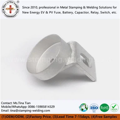
Two-Piece Fuse Cap Assemblies: Inner Cap Crimp and Outer Cap Solder Joint Engineering
Oct 29, 2026
Two-piece fuse cap assemblies combine a mechanically crimped inner copper cap with an outer cap joined to the fuse terminal or contact blade by high-frequency induction brazing. The design separates ceramic-tube retention and sealing from terminal attachment, allowing each interface to be controlled for dimensional fit, mechanical strength, and electrical continuity. Xiamen Apollo Stamping Welding Technology Co., Ltd. manufactures precision-stamped fuse caps and contact assemblies for industrial and automotive fuse applications, with project-specific validation of pull-off force, joint integrity, and plating performance.
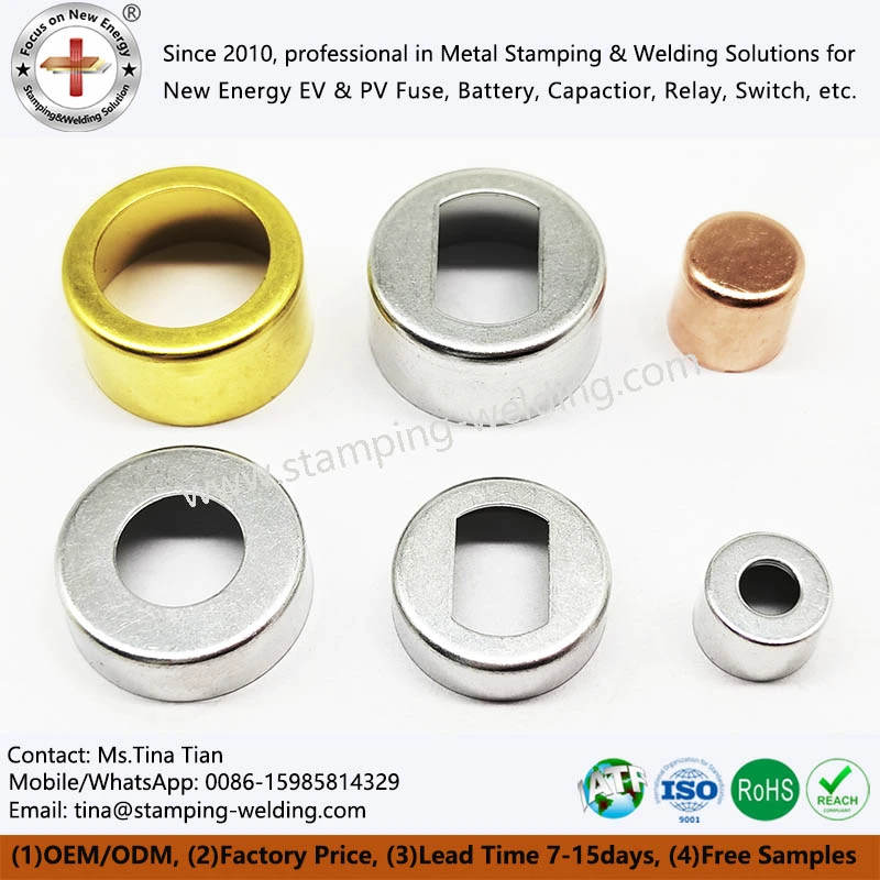
Why High-Interrupting-Capacity Fuses Use Two-Piece Copper End Caps
Functional Separation Between the Inner Cap and Outer Cap
High-voltage fuse assemblies must retain the ceramic tube, maintain terminal alignment, and withstand mechanical and thermal loads during normal operation and fault interruption. A two-piece end-cap design separates these functions into two interfaces.
Inner copper cap: Retains the ceramic tube through controlled mechanical crimping and provides the primary metal interface around the tube opening.
Outer copper cap: Forms the external terminal structure and provides the attachment interface for the contact blade or fuse terminal.
Nested cap interface: Establishes the dimensional relationship between the two components and supports concentric assembly.
Surface finish: Limits oxidation and supports electrical contact and soldering or brazing requirements where applicable.
The two-piece structure allows the inner cap to be optimized for ceramic retention while the outer cap is designed for terminal attachment. Whether it outperforms a single-piece cap depends on fuse geometry, interruption rating, manufacturing volume, and qualification results.
Two-Piece vs. Single-Piece Fuse Cap Manufacturing
| Engineering Factor | Two-Piece Copper Cap | Single-Piece Cap |
| Ceramic-tube retention | Dedicated inner-cap crimp | Formed directly into the cap |
| Terminal attachment | Separate outer-cap joining operation | Integrated or separately attached terminal |
| Tooling requirements | Separate tooling and assembly control | Potentially fewer components |
| Dimensional control | Requires nested-fit tolerance management | Depends on forming and terminal geometry |
| Joint inspection | Inner crimp and outer joint inspected separately | Fewer interfaces, but forming defects remain possible |
| Design flexibility | Independent optimization of each interface | More dependent on one-piece geometry |
For high-reliability applications, the correct architecture is the one that meets the specified interrupting capacity, mechanical retention, thermal performance, and sealing requirements. A two-piece structure is not inherently safer without supporting test data.
Copper Material Selection for Fuse Caps
Copper grade selection affects conductivity, formability, brazing behavior, and plating adhesion.
| Material | Primary Characteristics | Engineering Considerations |
| C11000 copper | High electrical conductivity and good thermal conductivity | Suitable for conductive cap and terminal structures where forming requirements permit |
| C10200 oxygen-free copper | High conductivity with controlled oxygen content | Considered where material and joining requirements justify its use |
| C26800 brass | Higher strength and good formability for many stamped geometries | Lower electrical conductivity than pure copper |
| Customer-specified copper alloy | Properties depend on composition and temper | Requires material-certificate verification |
Material selection should consider tube dimensions, crimp deformation, terminal current, joining temperature, and the required plating system.
Inner Copper Cap Crimping: Ceramic Retention and Pressure-Sealing Control
Mechanical Crimping Without Solder at the Ceramic Interface
The inner cap is mechanically formed around the ceramic tube opening. The crimp must retain the tube without producing excessive ceramic stress or leaving an unacceptable leakage path.
Unlike a soldered joint, a mechanical crimp does not depend on solder wetting or solidification. Its performance depends on cap geometry, material ductility, tube dimensional variation, and the deformation imposed during assembly.
Key process variables include:
Inner-cap wall thickness and forming allowance.
Ceramic tube outside diameter and end-face geometry.
Crimp depth and final crimp diameter.
Crimp tooling alignment and wear.
Copper temper and springback.
Ceramic edge condition and resistance to local cracking.
Crimp Geometry and Ceramic Fracture Prevention
Excessive crimp displacement can introduce concentrated radial and circumferential stresses into the ceramic tube. Insufficient deformation can result in weak retention, cap movement, or an inadequate sealing interface.
| Process Variable | Excessive Condition | Insufficient Condition |
| Crimp depth | Ceramic edge damage or cracking | Inadequate retention |
| Radial compression | Excessive ceramic stress | Cap loosening |
| Cap wall thickness | High forming force | Reduced structural support |
| Tool alignment | Localized loading | Uneven circumferential crimp |
| Tube dimensional variation | Local overload | Inconsistent fit |
The acceptable crimp window must be established through dimensional trials and mechanical testing. It should not be inferred from nominal cap dimensions alone.
Pressure Integrity and High-Voltage Fuse Interruption
During fault interruption, the fuse element melts and an arc forms inside the fuse body. The internal pressure and gas flow depend on fuse construction, filler material, element geometry, fault current, and interruption conditions.
The inner-cap crimp must therefore be qualified as part of the complete fuse assembly. A visually closed joint does not prove gas-tightness or pressure integrity.
Recommended verification includes:
Crimp diameter and profile measurement.
Axial retention or pull-off testing.
Ceramic inspection for cracks and edge damage.
Leak testing using a method appropriate to the fuse design.
Pressure or interruption testing at the specified qualification conditions.
Request Free DFM Evaluation & Quote
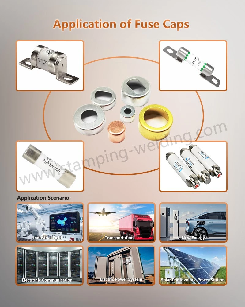
High-Frequency Induction Brazing: Outer Cap and Contact Blade Joining
Induction Brazing Process and Joint Formation
The outer cap is joined to the contact blade or terminal using a joining process selected for the material combination and component geometry. High-frequency induction brazing can provide localized heating without heating the entire fuse assembly to the same extent.
The process uses an alternating electromagnetic field to generate heat in a conductive workpiece or susceptor. A compatible brazing filler metal melts and wets the prepared joint surfaces, while the base metals remain substantially solid under correctly controlled brazing conditions.
The process window depends on:
Base-metal composition and surface condition.
Joint clearance and overlap geometry.
Brazing filler alloy and liquidus temperature.
Induction coil geometry and coupling distance.
Heating time and temperature distribution.
Flux selection or controlled-atmosphere requirements.
Cooling rate and post-joining cleaning.
Brazing parameters must be validated for the actual assembly. A frequency or heating-time value cannot be transferred reliably between different cap sizes and induction coil designs without process qualification.
Joint Strength and Pull-Off Force Above 500 N
A pull-off force requirement above 500 N can be used as a customer-defined mechanical acceptance criterion for the outer-cap joint. It is not a universal requirement for every fuse terminal.
The test specification should define the loading direction, gripping method, loading rate, sample conditioning, and failure classification.
| Test Condition | Required Definition | Purpose |
| Axial pull-off | Force direction relative to the joint | Measure terminal retention |
| Loading rate | Defined test speed | Improve result repeatability |
| Fixture design | Controlled gripping without distortion | Prevent fixture-induced failure |
| Failure mode | Base-metal fracture, joint separation, or deformation | Distinguish joining defects from component failure |
| Acceptance force | Greater than 500 N if specified | Verify mechanical retention |
| Sample plan | Defined production sampling or qualification plan | Establish process consistency |
A force result above 500 N does not by itself prove electrical continuity, sealing integrity, or high-current endurance. These characteristics require separate verification.
Brazing Defects and Process Controls
Common defects include incomplete filler-metal wetting, voids, excessive filler accumulation, joint misalignment, and local overheating.
| Defect | Likely Cause | Control Method |
| Incomplete wetting | Oxidized surfaces or unsuitable heating cycle | Surface preparation and thermal-profile control |
| Joint voids | Poor joint fit or trapped gas | Clearance and assembly control |
| Excessive filler metal | Incorrect filler placement or volume | Metered filler application |
| Cap distortion | Excessive or uneven heat input | Coil optimization and fixture control |
| Weak joint | Insufficient wetting or inadequate bonded area | Process validation and pull-off testing |
| Plating damage | Joining temperature exceeds finish capability | Sequence optimization and post-process inspection |
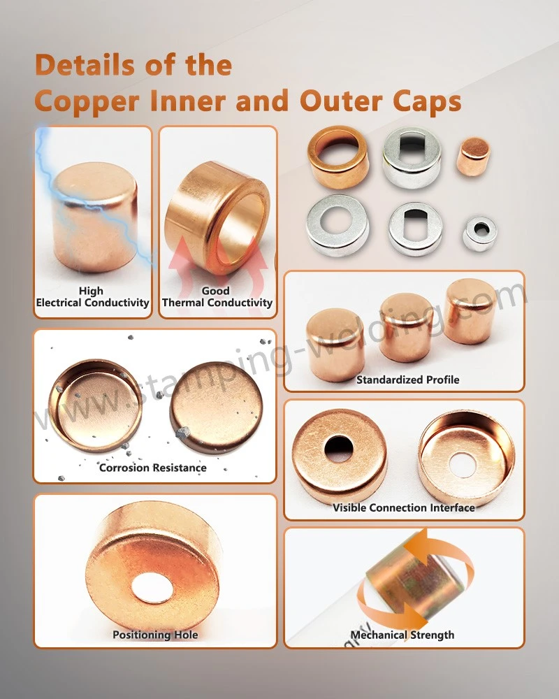
Nested Fit Tolerance of ±0.02 mm and Tin-Plating Process Control
Inner-to-Outer Cap Dimensional Matching
The nested interface between the inner and outer caps determines assembly alignment and affects the consistency of downstream joining operations.
A nominal fit tolerance of ±0.02 mm may be specified for selected critical dimensions, but the drawing must clarify whether the tolerance applies to an individual diameter, a positional characteristic, or the resulting clearance between two components.
The worst-case clearance is determined by the combined dimensional limits of both parts. If each component has an independent tolerance, the resulting assembly clearance cannot be assumed to remain within ±0.02 mm without a tolerance-stack calculation.
Bright Tin vs. Matte Tin Surface Finish
Tin plating helps protect copper surfaces against oxidation and can provide a solderable finish where the joint design requires it. Bright and matte tin finishes differ in deposit morphology and additive systems, but neither finish should be selected on appearance alone.
| Characteristic | Bright Tin | Matte Tin |
| Surface appearance | Reflective | Dull or low-reflectivity |
| Deposit additives | Commonly uses brightening additives | Generally lower-brightener formulation |
| Solderability | Depends on deposit quality, aging, and contamination | Depends on deposit quality, aging, and contamination |
| Whisker risk | Requires assessment based on plating system and stress | Also requires assessment; matte finish is not automatically whisker-free |
| Application selection | Based on validated finish specification | Based on validated finish specification |
The selected finish should be evaluated for plating thickness, coverage, adhesion, storage stability, and compatibility with the joining sequence.
Plating Thickness and Oxidation Protection
The required tin thickness must be defined by the component drawing or customer specification. Inspection may use X-ray fluorescence (XRF), metallographic cross-section analysis, or another validated method appropriate to the substrate and coating geometry.
Quality controls should include:
Plating thickness at defined measurement locations.
Coverage at edges and formed features.
Adhesion after forming and joining.
Surface discoloration and contamination.
Storage and solderability performance where applicable.
Plating sequence matters. If induction brazing is performed after tin plating, the thermal cycle may damage or redistribute the coating near the joint. If plating follows brazing, the assembly must be suitable for the plating bath and masking process. The manufacturing sequence should be established through process trials.
Request Free DFM Evaluation & Quote
Integrated Stamping and Joining for Two-Piece Fuse Cap Assemblies
Precision Stamping and Cap Forming
The inner and outer caps require forming operations that preserve concentricity, wall thickness, and the geometry needed for assembly.
Depending on the component design, the production route may include blanking, deep drawing, trimming, sizing, deburring, and final dimensional calibration.
The main quality characteristics are:
Cap diameter and height.
Wall thickness distribution.
Roundness and concentricity.
Crimping profile.
Contact-blade mounting geometry.
Burr height and edge condition.
The tooling design must account for copper grade, temper, material thickness, forming strain, and springback. Tool clearance and forming radii should be established through material-specific trials.
Assembly Flow and Quality Gates
A controlled production flow separates dimensional verification from joining and final assembly inspection.
| Manufacturing Stage | Critical Control | Verification |
| Copper material receipt | Grade, temper, and thickness | Material certificate and dimensional inspection |
| Inner-cap stamping | Profile and forming quality | Optical measurement |
| Outer-cap stamping | Fit dimensions and terminal interface | Dimensional inspection |
| Ceramic-tube crimping | Retention and ceramic integrity | Profile and mechanical testing |
| Induction brazing | Joint formation and alignment | Process monitoring and joint inspection |
| Tin plating | Thickness and coverage | XRF or validated coating measurement |
| Final assembly | Alignment and functional integrity | Visual and dimensional inspection |
| Qualification | Mechanical, electrical, and pressure performance | Customer-defined validation tests |
Quality Documentation for Automotive and Industrial Fuse Programs
Depending on the customer's quality requirements, the manufacturing package may include:
Process flow diagram.
Process Failure Mode and Effects Analysis (PFMEA).
Control plan.
Measurement-system analysis.
Dimensional inspection report.
Material and plating certificates.
Pull-off test results.
PPAP documentation, where contractually required.
IATF 16949 requirements apply to suppliers and manufacturing sites within the relevant certification scope. Certification status should be confirmed for the specific facility and product program rather than inferred from the component type.
OEM Selection Checklist for Two-Piece Fuse Cap Suppliers
Before tooling release, the buyer should define the fuse operating conditions and the dimensional, joining, and validation requirements.
| Procurement Input | Engineering Purpose |
| Fuse voltage and current rating | Establish electrical duty |
| Interrupting-capacity requirement | Define fault-interruption qualification |
| Ceramic tube dimensions | Establish crimp geometry |
| Inner and outer cap drawings | Define fit and functional tolerances |
| Contact-blade material | Confirm joining compatibility |
| Pull-off force requirement | Establish mechanical acceptance criteria |
| Leak or pressure test requirement | Define sealing validation |
| Tin-plating specification | Control coating thickness and coverage |
| Annual demand | Select tooling and production arrangement |
| PPAP and traceability requirements | Define production approval documentation |
Apollo manufactures precision-stamped fuse caps and contact assemblies, integrating copper-cap forming, mechanical crimping, induction brazing where specified, and plating coordination. Final acceptance should be based on approved drawings, qualified process parameters, and documented performance tests.
Frequently Asked Questions
1. What pull-off force can a two-piece fuse cap assembly achieve?
The required pull-off force depends on cap geometry, material, joint design, and test conditions. For projects specifying more than 500 N, the joint must be validated using a defined loading direction, fixture, and acceptance method.
2. How is the ±0.02 mm nested fit between inner and outer fuse caps controlled?
The fit is controlled through precision stamping, sizing, and dimensional inspection of both components. A tolerance-stack analysis is required to verify the resulting clearance between the inner cap and the outer cap.
3. How can a fuse cap supplier verify tin-plating thickness and joint integrity?
Tin thickness can be checked by XRF or a validated cross-section method. Joint integrity requires separate inspection and mechanical testing, such as pull-off testing, based on the approved component specification.
contact us