Laser Welding Optimization: Joining Nickel-Plated Copper Busbars to Prismatic Cell Terminals
Oct 27, 2026
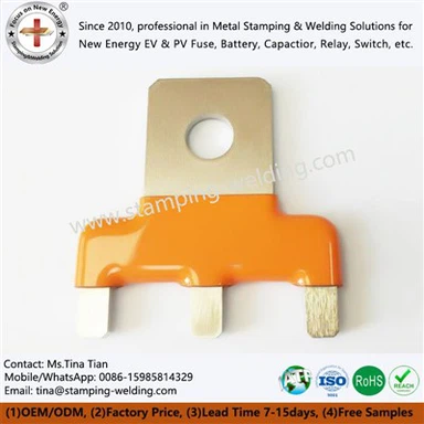
Nickel-plated copper busbars joined to prismatic cell terminals require precise control of laser energy density, surface reflectivity, weld penetration, and intermetallic compound formation. For copper-to-aluminum joints, the thickness and distribution of brittle Cu-Al intermetallic compounds (IMCs) directly affect joint resistance, shear strength, and fatigue performance under battery-pack vibration and thermal cycling.
Xiamen Apollo Stamping Welding Technology Co., Ltd. supports battery busbar terminal laser welding through material-specific process development, weld cross-section analysis, electrical resistance measurement, and mechanical joint validation. The welding procedure must be qualified against the actual busbar thickness, plating specification, terminal alloy, and cell sealing geometry rather than selected by laser power alone.
Laser Welding Challenges for Nickel-Plated Copper Busbars and Prismatic Cell Terminals
High Reflectivity and Thermal Conductivity of Copper
Copper presents two major challenges during laser welding: high reflectivity at common infrared laser wavelengths and rapid heat dissipation through its bulk material.
Nickel plating changes the surface absorption characteristics but does not eliminate the thermal behavior of the underlying copper. The plating thickness, surface oxidation, and local coating condition can also affect initial energy coupling.
| Material or Process Variable | Engineering Effect | Required Control |
| C1100 / C10200 copper busbar | High electrical and thermal conductivity | Verify material grade and temper |
| Nickel plating | Changes surface absorption and interface chemistry | Confirm plating thickness and uniformity |
| Aluminum cell terminal | Surface oxide and high thermal conductivity complicate fusion | Verify terminal alloy and oxide condition |
| Laser power density | Determines melting initiation and penetration | Establish a qualified process window |
| Welding speed | Changes line energy and thermal exposure | Validate against penetration and spatter |
| Clamping pressure | Affects interface gaps and joint repeatability | Control fixture geometry and force |
Copper's high thermal conductivity can cause heat to dissipate away from the weld zone before stable melting occurs. Once melting begins, excessive energy input may produce keyhole instability, metal vaporization, spatter, and local burn-through.
For battery-pack production, these defects can damage adjacent insulation or the cell's sealing components. The process window must therefore balance reliable fusion with limited heat transfer to the surrounding assembly.
Joint Configuration and Contact Geometry
The correct welding configuration depends on whether the joint is copper-to-copper, nickel-plated copper-to-aluminum, or another material combination.
| Joint Configuration | Primary Risk | Qualification Priority |
| Nickel-plated copper to copper terminal | Incomplete fusion or coating-related defects | Penetration and electrical resistance |
| Nickel-plated copper to aluminum terminal | Cu-Al intermetallic formation and brittle fracture | IMC morphology, thickness, and shear strength |
| Copper busbar to dissimilar-metal transition piece | Uneven heat flow and interface instability | Joint geometry and metallurgical compatibility |
The drawing should define the overlap length, weld location, allowable gap, terminal thickness, busbar thickness, and keep-out distance from the cell seal. These dimensions determine the available welding area and the risk of heat affecting the cell housing.
Blue, Green, and Infrared Laser Strategies for Reducing Spatter and Improving Fusion
Wavelength Selection for Copper Absorption
Laser wavelength influences how effectively the incident beam couples energy into copper. Blue and green lasers generally offer higher absorptivity on copper than near-infrared lasers under comparable surface conditions. Infrared fiber lasers remain widely used because of their power availability, beam delivery, and established industrial integration.
Hybrid or combined-wavelength systems can use these different absorption characteristics to improve process stability. The appropriate configuration depends on the required penetration depth, production rate, optical setup, and material combination.
| Laser Configuration | Main Advantage | Process Limitation | Typical Development Focus |
| Infrared fiber laser | High available power and established production integration | Higher initial copper reflectivity | Stable melting and keyhole control |
| Blue laser | Higher copper absorption at the incident surface | Power availability and process economics vary by system | Conduction-mode welding and controlled copper melting |
| Green laser | Improved copper energy coupling compared with near-infrared wavelengths | Equipment cost and optical integration | Reduced energy instability and spatter |
| Blue/infrared or green/infrared hybrid | Combines surface absorption with deeper penetration capability | Requires coordinated power and beam parameter control | Stable fusion across material interfaces |
Higher absorptivity does not automatically guarantee a defect-free joint. Beam diameter, focal position, scanning speed, power modulation, shielding conditions, and interface fit-up must be validated together.
Controlling Spatter Near Cell Sealing Components
Spatter occurs when rapid vaporization, unstable keyhole formation, or excessive melt-pool pressure ejects molten metal from the joint. In a prismatic cell assembly, ejected particles may contaminate the terminal surface, damage nearby insulation, or compromise sealing-area cleanliness.
The principal control variables include:
Laser power ramp-up and ramp-down profiles
Scanning speed and beam oscillation amplitude
Focal position and beam diameter
Gap between busbar and terminal
Clamping stability and local heat dissipation
Shielding gas type, flow, and nozzle orientation
A qualified welding window should define both the acceptable fusion range and the maximum permitted spatter level. Visual inspection alone cannot establish internal fusion quality.
Process Window Qualification Using Line Energy
For example, a 1,000 W laser operating at 100 mm/s gives a nominal line energy of 10 J/mm. This value is a process comparison metric, not a universal welding setpoint. Actual energy absorbed by the joint depends on wavelength, surface condition, beam profile, and material geometry.
Process qualification should use cross-section measurements and mechanical and electrical tests to determine the acceptable operating range.
Request Free DFM Evaluation & Quote
Cu-Al Intermetallic Compound Control for Battery Interconnect Reliability
Why Cu-Al Intermetallic Compounds Form During Welding
When copper and aluminum are fusion-welded, both materials can mix within the molten pool and react to form intermetallic phases. Depending on the local composition and thermal history, phases may include Al₂Cu, AlCu, and Al₄Cu₉.
These compounds generally have lower ductility than the parent metals. A continuous, thick, or crack-containing intermetallic region can become a preferential fracture path under shear loading, vibration, and thermal cycling.
The objective is not necessarily to eliminate all intermetallic formation. It is to control the joint microstructure so that metallurgical bonding is achieved without excessive brittle-phase growth.
Establishing a 5 µm Intermetallic Layer Target
A maximum intermetallic layer thickness of 5 µm may be adopted as a project-specific engineering target where the joint design and metallurgical validation support it. It should not be treated as a universal requirement for every copper-aluminum laser weld.
The acceptance criterion must specify how thickness is measured, where the interface is sampled, and whether the limit applies to the maximum local thickness or a statistical average.
| Process Variable | Effect on Cu-Al Interface | Control Strategy |
| Peak temperature | Influences reaction kinetics and local melting | Adjust laser power and beam profile |
| Time at elevated temperature | Longer exposure can increase diffusion and reaction-layer growth | Optimize speed and thermal cycle |
| Copper-aluminum mixing ratio | Determines local phases and solidification behavior | Control beam position and weld geometry |
| Beam oscillation | Changes mixing, pool dimensions, and heat distribution | Validate amplitude and frequency |
| Interface gap | Causes inconsistent energy transfer and fusion | Use controlled clamping and dimensional inspection |
| Post-weld cooling | Affects solidification structure and residual stress | Validate process-dependent cooling conditions |
A low-heat-input strategy can limit excessive intermetallic growth, but insufficient energy may cause incomplete fusion or a weak interface. Both conditions must be assessed through metallography and mechanical testing.
Metallographic Verification of the Weld Interface
Cross-section analysis should include specimens taken from representative positions along the weld. Sample preparation must preserve the interface and avoid polishing artifacts that could be mistaken for cracks or pores.
Recommended examination criteria include:
Fusion-zone width and penetration depth
Interfacial continuity and local reaction-layer thickness
Porosity, cracks, and incomplete fusion
Evidence of excessive material mixing
Microstructure variation between the weld center and edges
Optical microscopy can identify major defects and measure the overall fusion profile. Scanning electron microscopy (SEM), with suitable compositional analysis where required, can help distinguish intermetallic regions and assess local interface chemistry.
Electrical Resistance, Temperature Rise, and Mechanical Qualification
Four-Wire Micro-Resistance Measurement
Joint resistance is a key indicator of electrical connection quality. Excessive resistance increases localized Joule heating under current load:
For example, a joint resistance of 10 µΩ at 300 A produces 0.9 W of heat. At 500 A, the same resistance produces 2.5 W. These calculations assume constant resistance; actual resistance changes with temperature and operating conditions.
Four-wire Kelvin measurement is recommended for low-resistance joints because it reduces the influence of lead and probe resistance. The test procedure should define probe positions, test current, temperature, stabilization time, and instrument accuracy.
Acceptance limits must be established from the busbar geometry, rated current, allowable temperature rise, and cell-terminal requirements.
Temperature-Rise Testing Under Rated Current
A low room-temperature resistance value does not by itself establish thermal suitability. Temperature-rise testing should reproduce the intended current path and relevant boundary conditions.
| Test Variable | Required Definition | Purpose |
| Test current | Rated or specified overload current | Reproduce electrical loading |
| Ambient temperature | Controlled test environment | Enable valid comparisons |
| Measurement location | Weld zone and adjacent terminal | Detect localized heating |
| Stabilization criterion | Defined temperature-change threshold | Ensure repeatable results |
| Thermal boundary conditions | Fixture, cooling, and conductor geometry | Represent the intended application |
Infrared thermography can identify temperature distribution, while thermocouples can provide contact-based measurements. Emissivity settings must be considered when measuring reflective metal surfaces using infrared cameras.
Tensile, Shear, and Peel Testing of Laser-Welded Joints
Mechanical testing should reflect the actual load path rather than rely on one universal pull-force requirement.
For lap joints, shear testing measures resistance to in-plane loading. Peel or pull testing can reveal weak interface bonding and local fracture behavior, but results depend strongly on specimen geometry and loading direction.
A qualification plan should specify:
Specimen dimensions and weld length
Loading direction and test speed
Peak force and displacement at failure
Failure location and fracture mode
Sample size and acceptance criteria
For battery applications, vibration and thermal cycling tests may be added to assess joint durability under service conditions. Test levels should follow the customer's validation plan and applicable product requirements.
Request Free DFM Evaluation & Quote
Manufacturing Controls for Prismatic Cell Busbar Joining OEM Programs
Joint Design and Manufacturability Review
Before welding trials, Apollo reviews the busbar drawing, terminal material, plating specification, joint overlap, electrical current requirement, and surrounding cell geometry.
The design-for-manufacturing review should address:
Access for the laser head and shielding nozzle
Clamping repeatability and interface gap
Weld path clearance from cell seals and insulation
Busbar flatness and terminal position tolerance
Inspection access and test-point definition
These inputs determine whether the proposed joint can be welded and inspected consistently in production.
Process Validation and Production Quality Records
A controlled welding process requires documented parameters, traceable material inputs, and defined acceptance criteria. For automotive programs, quality documentation may be aligned with IATF 16949 requirements and customer-specific PPAP submissions, including PPAP Level 3 when required by the customer.
| Quality Control Stage | Verification Method | Record or Output |
| Incoming material | Alloy and plating verification | Material certificates and inspection records |
| Setup validation | Parameter and fixture checks | Approved welding recipe |
| First-article inspection | Dimensional and visual inspection | First-article report |
| Destructive qualification | Metallography and mechanical testing | Cross-section and strength reports |
| Electrical validation | Four-wire resistance and temperature-rise tests | Electrical test report |
| Production monitoring | Defined sampling and process checks | Traceability and inspection records |
The specific sampling frequency, control limits, and document package should be agreed upon during the quality planning stage. IATF 16949 alignment does not replace application-specific weld qualification.
Prototype-to-Mass-Production Transfer
A prototype weld that passes inspection is not automatically suitable for high-volume production. Transfer requires confirmation that the approved process remains stable across material lots, tooling conditions, fixture changes, and equipment maintenance intervals.
For Prismatic Cell Busbar Joining OEM programs, the release plan should include:
1. Drawing and material specification review
2. Initial welding trials and parameter screening
3. Metallographic, electrical, and mechanical validation
4. Repeatability assessment across multiple samples or production runs
5. Control-plan approval and customer-specific PPAP submission
6. Ongoing monitoring of weld appearance, resistance, and critical dimensions
Material and Process Selection for Nickel-Plated Copper and Cu-Al Battery Interconnects
Copper and Aluminum Joint Considerations
Copper and aluminum offer different electrical, thermal, and mechanical characteristics. Their joining process must account for the conductivity target, mass constraint, galvanic compatibility, and interface metallurgy.
| Design Factor | Copper Busbar | Aluminum Terminal or Busbar |
| Electrical conductivity | High; grade-dependent | Lower than high-conductivity copper for equivalent cross-section |
| Density | Approximately 8.9 g/cm³ | Approximately 2.7 g/cm³ |
| Thermal conductivity | High | High, but generally lower than copper |
| Laser welding concern | Reflectivity and rapid heat dissipation | Oxide film and Cu-Al intermetallic formation |
| Key validation | Fusion, resistance, and heat input | Fusion, interface integrity, and intermetallic control |
Nickel plating may be specified to address contact-surface requirements, corrosion behavior, or assembly compatibility. It does not eliminate the need to qualify the underlying copper-aluminum interface.
Recommended Qualification Matrix
The qualification matrix should be agreed upon before tooling release or mass-production approval.
| Qualification Item | Method | Acceptance Basis |
| Weld penetration | Metallographic cross-section | Drawing and validated process limits |
| Intermetallic layer | Optical microscopy / SEM as required | Project-specific thickness and morphology limits |
| Joint resistance | Four-wire Kelvin measurement | Electrical design specification |
| Temperature rise | Rated-current test | Maximum permitted joint temperature |
| Mechanical strength | Shear, tensile, or peel test | Customer-defined minimum load and failure mode |
| Spatter | Visual or magnified inspection | Defined keep-out zones and defect limits |
| Process repeatability | Multi-sample or multi-run evaluation | Approved control plan |
Apollo OEM Welding Support for Battery Busbar Assemblies
Xiamen Apollo Stamping Welding Technology Co., Ltd. supports precision metal stamping and welding components for EV, ESS, and power-electronics applications. Battery interconnect projects can be evaluated using the customer's material specifications, drawings, electrical requirements, and validation criteria.
For an initial engineering review, provide:
Busbar and cell-terminal drawings in STEP, DXF, or PDF format
Copper alloy, aluminum alloy, and nickel-plating specifications
Material thicknesses and joint overlap dimensions
Rated current and allowable temperature rise
Required resistance, mechanical strength, and leak or sealing constraints
Annual volume, prototype quantity, and customer-specific quality requirements
Apollo can use these inputs to assess joint geometry, identify process risks, define a prototype welding plan, and establish the inspection requirements for qualification.
FAQ
What is the target intermetallic layer thickness for Cu-Al battery busbar laser welding?
A limit of 5 µm can be used as a project-specific target when supported by metallographic and mechanical validation. The specification must define the measurement location, sampling method, and whether the limit applies to maximum local thickness or average thickness.
How is battery busbar laser welding joint resistance measured accurately?
Use four-wire Kelvin measurement with defined probe locations, test current, and temperature conditions. Confirm the resistance limit against rated current, allowable temperature rise, conductor geometry, and customer requirements.
What tests are required to qualify prismatic cell busbar joining for mass production?
A typical plan includes weld cross-section analysis, visual and spatter inspection, micro-resistance measurement, temperature-rise testing, and mechanical shear or peel testing. Vibration and thermal cycling may also be required by the customer validation plan.
contact us