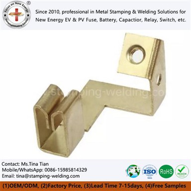
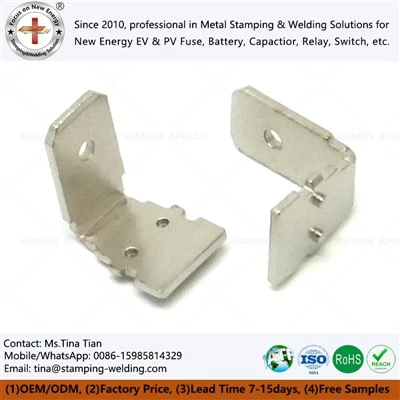
Precision Electron Beam Welded Copper-Manganin Current Shunt Resistors for BMS
Oct 28, 2026
Copper-manganin current shunt resistors convert high current into a measurable millivolt signal for battery management systems (BMS) and intelligent battery sensors (IBS). Their accuracy depends on the manganin resistance element, copper terminal geometry, joint resistance, temperature coefficient of resistance (TCR), and long-term thermal stability. Xiamen Apollo Stamping Welding Technology Co., Ltd. supports OEM production through precision terminal stamping, copper-to-manganin joining, resistance calibration, and dimensional inspection, with project targets including TCR below 20 ppm/°C and initial resistance tolerance of ±1%.
BMS Current Measurement Requirements: Micro-Ohm Resistance and ±1% Accuracy
How a Copper-Manganin Shunt Measures Battery Current
A shunt resistor measures current through the voltage drop generated across a calibrated resistance element. The relationship follows Ohm's law:
For example, a 100 µΩ shunt produces a 10 mV signal at 100 A and 20 mV at 200 A. These values are calculated examples, not universal BMS design requirements.
The low resistance limits power dissipation while preserving a signal that the battery monitor's analog front end can measure.
At 200 A through a 100 µΩ shunt, the dissipated power is 4 W. Thermal design must account for the copper terminals, manganin element, welded interfaces, mounting conditions, and heat transfer into the busbar or battery assembly.
| Design Parameter | Example or Target | Engineering Significance |
| Nominal resistance | 100 µΩ | Determines voltage output |
| Current | 100–200 A | Defines measurement and thermal load |
| Output at 100 A | 10 mV | Analog front-end input signal |
| Power at 200 A | 4 W | Determines thermal rise |
| Initial resistance tolerance | ±1% | Sets initial current measurement error |
| TCR | Below 20 ppm/°C | Limits resistance change with temperature |
These figures illustrate one design point. Actual current range, resistance, overload capacity, and allowable temperature rise must be defined by the customer's electrical specification.
Resistance Tolerance and BMS Measurement Error
For a nominal 100 µΩ shunt with a ±1% initial tolerance, the resistance can range from 99 µΩ to 101 µΩ before other error sources are considered.
At a fixed measured voltage, calculated current is inversely proportional to the assumed shunt resistance. A resistance error therefore translates directly into a current measurement error of approximately the same magnitude, with opposite sign for a small deviation.
The complete BMS measurement error budget also includes:
Analog-to-digital converter gain and offset errors.
PCB copper trace resistance and sensing-point placement.
Thermoelectric voltages at dissimilar-metal junctions.
Common-mode voltage and electromagnetic interference.
Shunt self-heating and temperature gradients.
A precision shunt should therefore be evaluated as part of the complete Kelvin measurement circuit rather than as an isolated resistance component.
Electron Beam Welding of Copper and Manganin: Joint Integrity and Heat-Affected Zone Control
Why Copper-to-Manganin Joining Requires Process Control
Copper terminals provide a low-resistance electrical interface and a practical mounting structure. Manganin, a copper-based resistance alloy, provides a more stable resistance element than ordinary copper over a defined temperature range.
The two materials serve different electrical functions. The joining process must preserve the manganin element's resistance characteristics while minimizing unwanted resistance at the interface.
Copper has high thermal conductivity, while manganin has different thermal and electrical properties. During welding, these differences affect heat distribution, melting behavior, and cooling rate.
Potential defects include:
Excessive melting or local thinning of the manganin strip.
Incomplete fusion or lack of bonding.
Porosity and internal discontinuities.
Cracking caused by local thermal and mechanical stresses.
Local resistance variation near the joint.
Electron beam welding can provide a concentrated heat source and a narrow weld profile under suitable vacuum and process conditions. However, the weld geometry, penetration, material preparation, and thermal cycle must be validated for the actual copper-manganin combination.
Electron Beam Welding Versus Laser Welding for Shunt Assemblies
Both processes can be considered for joining copper terminals to a manganin element. The appropriate choice depends on joint geometry, required penetration, production volume, equipment configuration, and qualification results.
| Comparison Factor | Electron Beam Welding | Laser Welding |
| Energy delivery | Focused electron beam, normally under vacuum | Focused optical beam, commonly in a controlled atmosphere |
| Heat input | Concentrated; controlled through beam parameters and travel speed | Concentrated; controlled through power, speed, and beam profile |
| Joint access | Requires a suitable vacuum chamber and fixturing | Often easier to integrate into automated production cells |
| Copper processing | Requires validation of beam parameters and surface condition | Requires management of copper's reflectivity and thermal conductivity |
| Heat-affected zone | Depends on penetration, heat input, and cooling | Depends on power density, travel speed, and joint design |
| Production considerations | Vacuum cycle and chamber loading affect throughput | Automation, shielding, and optical access affect throughput |
| Qualification | Weld cross-sections, resistance, mechanical strength, and thermal stability | Weld cross-sections, resistance, mechanical strength, and thermal stability |
No process should be selected solely on the assumption that it always produces a smaller heat-affected zone. Comparative weld trials are needed to establish joint quality and resistance stability.
Weld Qualification for Low-Resistance Electrical Interfaces
The welded joint must carry the rated current without generating an excessive local temperature rise or introducing unacceptable measurement error.
A practical validation plan includes:
1. Metallographic cross-section: Examine penetration, fusion boundaries, porosity, and local material thinning.
2. Four-wire resistance measurement: Characterize the shunt resistance and monitor joint-related variation.
3. Mechanical testing: Verify joint strength against the specified loading condition.
4. Thermal testing: Measure temperature rise at rated current and defined ambient conditions.
5. Resistance stability testing: Compare resistance before and after thermal cycling and current loading.
The acceptance criteria should be established from the drawing and customer specification. Weld penetration and pull strength alone cannot demonstrate that the complete shunt meets its electrical accuracy requirements.
Request Free DFM Evaluation & Quote

Low TCR Below 20 ppm/°C: Resistance Stability Under Thermal Loading
Calculating Resistance Drift with Temperature
The temperature coefficient of resistance describes the relative change in resistance with temperature. For a limited temperature interval, the first-order approximation is:
If a shunt achieves a TCR of 20 ppm/°C and experiences a 50°C temperature change, the first-order resistance change is approximately 0.1%, assuming the stated TCR remains valid over that interval.
This calculation does not include self-heating gradients, weld-interface changes, thermoelectric offsets, or mechanical stress effects.
Manganin Grade Selection and Thermal Stability
Manganin is used for precision resistance elements because its resistance can remain relatively stable over a specified temperature range.
Actual TCR depends on alloy composition, material condition, processing history, operating temperature, and the resistance element's mechanical stress.
The alloy designation alone does not establish a guaranteed TCR below 20 ppm/°C. That limit must be confirmed for the selected material and operating range.
| Material or Feature | Electrical Function | Qualification Requirement |
| Copper terminal | Conducts current into and out of the element | Conductivity and dimensional verification |
| Manganin element | Establishes calibrated resistance | Resistance and TCR characterization |
| Welded interface | Transfers current between dissimilar materials | Joint integrity and resistance stability |
| Stamped terminal geometry | Defines mounting and current distribution | Dimensional and flatness inspection |
| Finished assembly | Provides the BMS measurement signal | Four-wire calibration and thermal testing |
Preventing Long-Term Zero-Point Drift in BMS and IBS Applications
In a current-measurement circuit, zero-point drift is not necessarily caused by the shunt resistance alone. The measured signal can shift because of amplifier offset, thermoelectric voltage, temperature gradients, and changes in electrical connections.
For a 100 µΩ shunt, a 1 µV offset corresponds to 10 mA of apparent current. This is why low-level offset behavior matters in applications requiring accurate current integration over long periods.
The validation plan should separate:
Shunt resistance change.
Weld-interface resistance change.
Temperature-dependent offset.
Analog front-end offset and gain drift.
Installation-dependent thermoelectric effects.
Recommended testing includes repeated four-wire resistance measurements, temperature cycling, rated-current operation, and post-test calibration against a traceable reference.
Precision Stamping and Micro-Ohm Resistance Trimming: Achieving ±1% Tolerance
Continuous Stamping of Copper Terminals
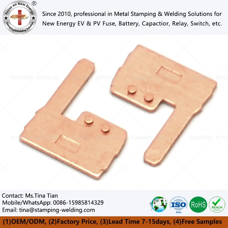
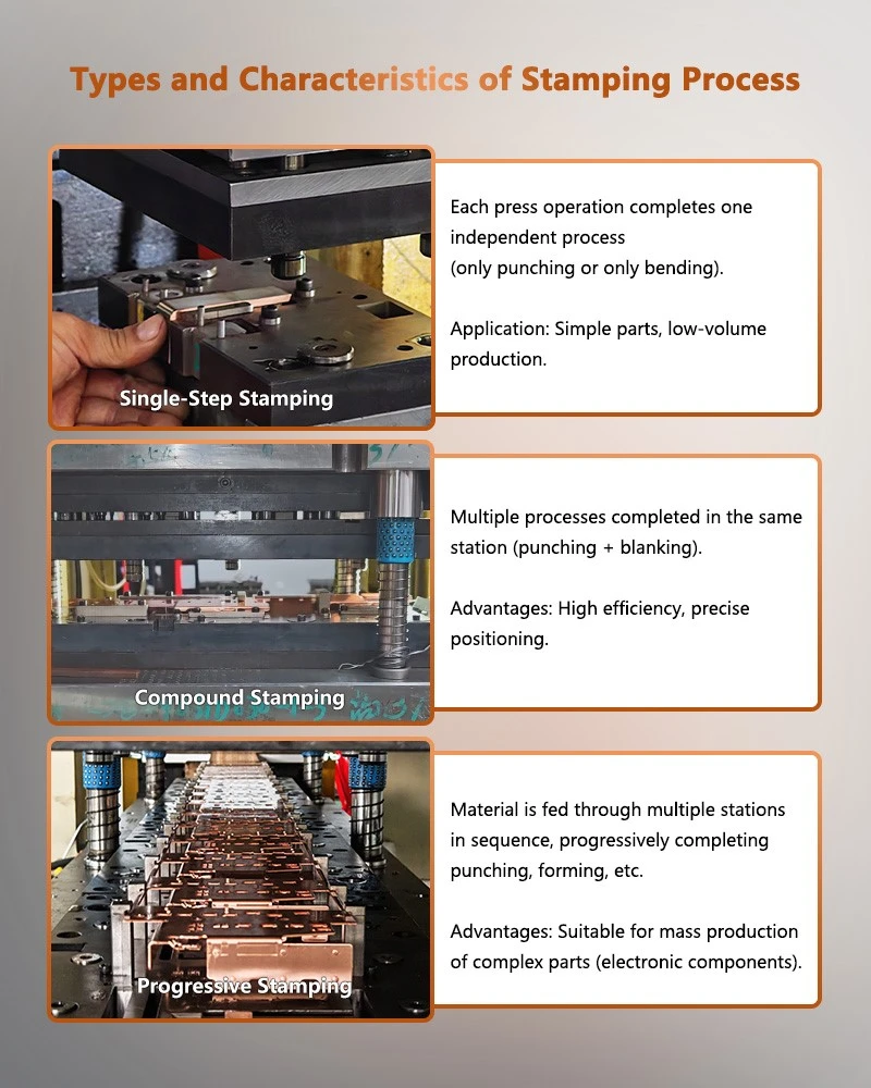
Precision stamping provides repeatable terminal geometry for high-volume current shunt production. The terminal design must support electrical conduction, weld accessibility, mounting stiffness, and consistent assembly positioning.
The main manufacturing variables include:
Copper grade and incoming strip thickness.
Punch-to-die clearance and cutting-edge condition.
Burr height and burr orientation.
Terminal flatness and mounting-hole position.
Weld-area cleanliness and surface condition.
Strip feeding accuracy and die alignment.
These variables affect both dimensional repeatability and the consistency of the welded assembly.
| Stamping Characteristic | Possible Effect on Shunt Performance | Inspection Method |
| Terminal width and thickness | Changes current distribution and heat dissipation | Micrometer or optical measurement |
| Mounting-hole position | Changes assembly alignment | Optical inspection or CMM |
| Flatness | Affects mounting contact and mechanical stress | Flatness measurement |
| Burr height | Can interfere with assembly or insulation | Optical or tactile measurement |
| Weld-zone geometry | Affects fit-up and joint repeatability | Profile inspection |
| Material condition | Influences forming and weld behavior | Material certificate and incoming inspection |
Laser Resistance Trimming and Four-Wire Calibration
The resistance of a completed shunt depends on the manganin element's dimensions, alloy properties, and the electrical contribution of the joints and terminals within the measurement span.
Laser trimming can remove controlled material from a designated trimming region to increase resistance toward the target value. It is not a substitute for correcting unstable welds, inconsistent material, or poorly defined voltage-sensing locations.
A suitable production sequence is:
1. Stamp copper terminals to drawing requirements.
2. Prepare and inspect the manganin resistance element.
3. Join the copper and manganin components using the qualified welding process.
4. Measure resistance using a four-terminal method.
5. Apply controlled laser trimming where the design permits.
6. Re-measure resistance and verify the final tolerance.
7. Record calibration results against the part or production lot.
A Kelvin four-wire measurement separates current-carrying leads from voltage-sensing leads, reducing the influence of lead resistance on the measured value.
The measurement current must be selected to prevent excessive self-heating during calibration. For micro-ohm components, fixture contact repeatability, thermal equilibrium, and instrument resolution also affect the result.
Controlling the ±1% Resistance Acceptance Window
For a nominal 100 µΩ shunt, this corresponds to 99–101 µΩ at the specified reference temperature and measurement conditions.
The production control plan should define:
Reference temperature and stabilization time.
Measurement current and instrument accuracy.
Kelvin sensing-point locations.
Allowed trimming range.
Rejection limits and rework rules.
Calibration record retention and traceability.
Request Free DFM Evaluation & Quote
OEM Manufacturing Validation for Copper-Manganin BMS Shunt Resistors
Critical-to-Quality Characteristics for Production Release
For a Copper Manganin Current Shunt Manufacturer, the finished electrical performance must be linked to measurable process characteristics.
| CTQ Characteristic | Verification Method | Acceptance Basis |
| Initial resistance | Four-wire Kelvin measurement | Customer drawing, such as ±1% |
| TCR | Resistance measurement over specified temperatures | Approved material and assembly specification |
| Weld integrity | Metallography and mechanical testing | Qualified joint criteria |
| Terminal dimensions | Optical measurement or CMM inspection | Released drawing |
| Rated-current temperature rise | Controlled current-load test | Thermal design limit |
| Resistance after cycling | Pre-test and post-test measurement | Defined drift limit |
| Lot traceability | Production and calibration records | Customer quality requirements |
Process Traceability and PPAP Documentation
Automotive and energy-storage customers may require a production qualification package covering material, tooling, welding, calibration, and inspection.
Depending on the program, documentation can include:
Material certificates for copper and manganin.
Process flow diagrams and control plans.
Dimensional inspection reports.
Welding procedure and qualification records.
Resistance calibration data.
Measurement system analysis.
Process capability studies.
PPAP Level 3 submission, when specified by the customer.
PPAP Level 3 requirements depend on the applicable customer-specific requirements and the agreed submission scope. The documentation should reflect the actual manufacturing process and validated production data.
Engineering Inputs for OEM Shunt Development
To establish a manufacturable shunt design, the customer should provide the following inputs wherever available:
| Input | Purpose |
| Nominal resistance and tolerance | Defines electrical calibration limits |
| Continuous and peak current | Establishes electrical and thermal loading |
| Operating temperature range | Defines TCR and thermal validation |
| Copper terminal drawing | Defines mounting and connection geometry |
| Manganin grade and thickness | Establishes resistance-element properties |
| Weld location and geometry | Defines joining and inspection requirements |
| Kelvin sensing locations | Controls the measurement span |
| Annual demand and traceability requirements | Determines production and quality planning |
Apollo's manufacturing scope can combine precision stamped copper terminals, qualified copper-manganin welding, dimensional inspection, and resistance calibration. Final performance values must be established through design review and validation of the complete shunt assembly.
FAQ
Q: 1. Can a copper-manganin BMS shunt resistor achieve a TCR below 20 ppm/°C?
A: Yes, if the selected manganin grade, operating temperature range, mechanical condition, and finished assembly meet the specified limit. The TCR must be verified by resistance measurements at defined temperatures rather than inferred from the alloy name alone.
Q: 2. How is ±1% resistance tolerance verified for a micro-ohm current shunt?
A: Use a calibrated four-wire Kelvin measurement system under controlled temperature and measurement-current conditions. Verify the finished assembly after welding and trimming, and retain traceable resistance results for each required production sample or lot.
Q: 3. What should buyers specify when requesting an OEM copper-manganin shunt quotation?
A: Provide nominal resistance, continuous and peak current, operating temperature range, terminal drawing, manganin specification, weld requirements, sensing-point locations, annual volume, and required PPAP documentation. These inputs establish the basis for tooling, process selection, and qualification testing.
contact us