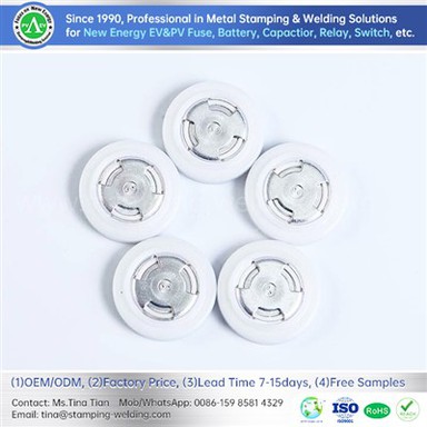
Silver-Copper Vacuum Brazing for High-Breaking-Capacity NH Industrial Fuse Knife Contacts
Oct 25, 2026
NH fuse knife contacts must maintain low electrical resistance, mechanical retention, and thermal stability during high-current operation and fault interruption. For industrial fuse systems rated up to 690 V or 1,000 V, with specified breaking capacities reaching 120 kA, silver-brazed copper contact assemblies require controlled joint geometry, filler-metal wetting, and verified bonding integrity. Xiamen Apollo Stamping Welding Technology Co., Ltd. manufactures precision stamped copper components and brazed contact assemblies for industrial fuse and power-distribution applications, with process qualification defined by the customer's drawings and validation requirements.
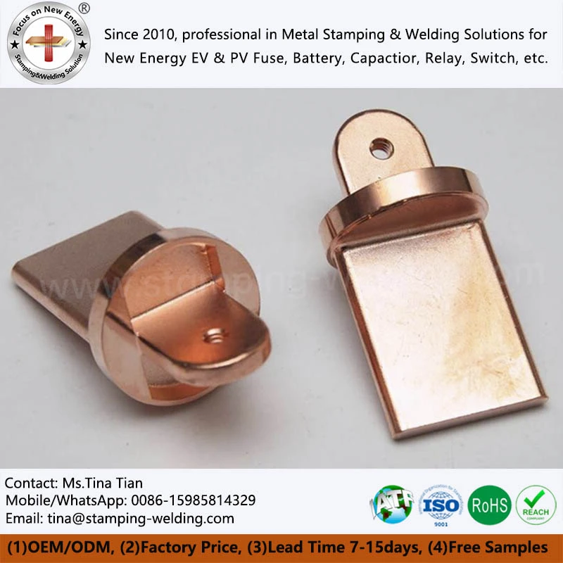
Engineering Requirements for NH Fuse Knife Contacts at 120 kA Breaking Capacity
Electrical and Mechanical Loads During Fault Interruption
NH industrial fuses are used in low-voltage power distribution, industrial motor protection, photovoltaic combiner systems, and energy storage power-conversion equipment. During a short circuit, the fuse element generates heat and melts, while the circuit experiences intense electromagnetic forces until the arc is extinguished.
The knife contact assembly must retain its electrical and mechanical characteristics throughout this event.
Three engineering requirements govern contact performance:
Low contact resistance: Minimize resistive heating at the fuse-to-holder interface and within the brazed joint.
Mechanical joint integrity: Resist electromagnetic repulsion, vibration, handling loads, and thermal cycling without separation.
Thermal stability: Maintain joint strength and conductivity under rated-current heating and specified overload conditions.
A breaking-capacity rating of 120 kA describes the maximum prospective fault current a fuse can interrupt under its specified test conditions. It does not, by itself, define the continuous-current rating, allowable temperature rise, or mechanical load on the brazed joint.
| Design parameter | Engineering significance | Verification method |
| Rated operational voltage: 690 V / 1,000 V | Defines the intended electrical operating conditions | Rated-voltage and applicable fuse-standard verification |
| Breaking capacity: up to 120 kA | Defines the specified fault-interruption capability | Short-circuit interruption test |
| Joint electrical resistance | Determines localized \(I^2R\) heating | Four-wire Kelvin resistance measurement |
| Contact temperature rise | Evaluates thermal performance under rated current | Thermocouple measurement or calibrated thermal imaging |
| Brazed-joint strength | Measures resistance to mechanical separation | Tensile or shear testing |
| Joint continuity | Identifies incomplete bonding or separation | Ultrasonic inspection and destructive sectioning |
The complete fuse assembly-not the brazed contact alone-must satisfy the applicable requirements of IEC 60269. Component-level tests establish process capability but do not replace final fuse qualification.
Copper Substrate Selection for Industrial Fuse Blade Contacts
Copper provides the electrical conduction path between the fuse element assembly and the external circuit. The substrate must also withstand stamping deformation, brazing temperatures, and subsequent assembly operations.
| Material | Main characteristics | Typical selection considerations |
| C11000 / equivalent high-conductivity copper | High electrical conductivity and thermal conductivity | Suitable for current-carrying contact components |
| C10200 oxygen-free copper | High conductivity and low oxygen content | Consider where joining requirements and material specifications favor oxygen-free copper |
| C2680 brass | Higher strength and formability, generally lower conductivity than pure copper | Suitable for selected structural or auxiliary parts rather than conductivity-critical blades without electrical validation |
Material selection must account for temper, thickness, forming direction, joint configuration, and post-brazing properties. Conductivity should be verified against the actual material specification rather than assumed from the alloy designation alone.
Even a small increase in joint resistance can create significant localized heating at high continuous current. Resistance measurements therefore need controlled contact pressure, a defined measurement location, and repeatable test temperature.
AWS BAg-7 Silver Brazing: Filler Metal and Process Window
Filler-Metal Selection for Copper Contact Assemblies
AWS BAg-7 is a silver-based brazing filler metal containing silver, copper, zinc, and tin. Its nominal composition is approximately 56% Ag, 22% Cu, 17% Zn, and 5% Sn by mass, subject to the applicable filler-metal specification.
Its relatively low brazing temperature and flow characteristics make it a candidate for joining compatible copper components where joint clearance, surface preparation, and thermal exposure are properly controlled.
| Property | AWS BAg-7 engineering consideration |
| Filler-metal family | Silver-copper-zinc-tin alloy |
| Nominal silver content | Approximately 56 wt.% |
| Nominal brazing temperature | Approximately 650°C, depending on specification and process conditions |
| Primary function | Fill the designed joint clearance through capillary action |
| Process variables | Joint gap, surface cleanliness, temperature, time, atmosphere and filler volume |
| Main risks | Incomplete wetting, voids, excessive filler flow, erosion and distortion |
The designation "silver brazing" does not mean that the joint consists of pure silver. Joint conductivity and mechanical strength depend on the filler alloy, bonded area, residual joint geometry, and quality of the copper-to-filler interface.
For applications with restricted zinc content, vacuum compatibility requirements, or specific environmental constraints, the filler-metal composition and brazing atmosphere must be reviewed before selecting BAg-7.
Vacuum Brazing Versus Medium-Frequency Induction Brazing
Vacuum brazing and medium-frequency induction brazing can both be used for copper contact assemblies, but they solve different production problems. The selection depends on component geometry, throughput, joint accessibility, and atmosphere requirements.
| Process factor | Vacuum brazing | Medium-frequency induction brazing |
| Heating method | Furnace heating under controlled vacuum | Electromagnetic induction heating |
| Temperature uniformity | Suitable for batch processing of multiple assemblies | Depends on coil design and part geometry |
| Oxidation control | Vacuum limits oxidation when the process is properly controlled | Often requires flux or a controlled protective atmosphere |
| Localized heating | Limited; the complete assembly is heated | Strong potential for localized heating |
| Production format | Batch processing | Suitable for automated or semi-automated stations |
| Primary process risks | Furnace uniformity, fixture loading, and filler migration | Uneven coupling, localized overheating, and coil-position variation |
| Validation priority | Furnace mapping and joint consistency | Heating repeatability, temperature profile, and joint consistency |
Vacuum brazing is not automatically flux-free in every configuration, and vacuum alone does not guarantee oxide-free copper surfaces.
Surface condition, furnace pressure, temperature profile, material compatibility, and any required surface treatment must be validated.
For high-volume industrial fuse contacts, induction brazing may offer shorter cycle times. Vacuum brazing may be preferable when multiple joints require controlled batch heating or when the assembly design benefits from a low-oxidation atmosphere.
Request Free DFM Evaluation & Quote
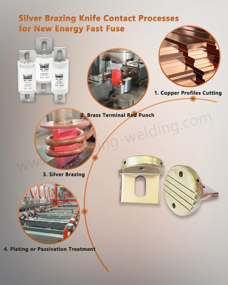
Brazed-Joint Integrity: Void Detection, Wetting and Effective Bonded Area
Why Joint Voids Matter in High-Current Contact Assemblies
A brazed joint transfers electrical current and mechanical load across the interface between copper components. Incomplete filler penetration or trapped voids reduce the effective bonded area and can concentrate both current density and mechanical stress.
The resulting failure mechanisms include:
Localized resistive heating at constricted current paths.
Crack initiation at void boundaries during thermal cycling.
Reduced shear capacity under mechanical loading.
Progressive joint degradation caused by repeated temperature excursions.
A nominal bonded-area target above 95% may be adopted as an internal process acceptance criterion for a defined joint design. However, this value is not a universal IEC 60269 requirement. The inspection method, evaluated area, allowable defect size, and acceptance threshold must be agreed upon in the control plan.
Ultrasonic C-Scan and Metallographic Validation
Ultrasonic C-scan inspection can map variations in acoustic response across a joint and help identify areas potentially associated with incomplete bonding or voids. Its reliability depends on the geometry, material thickness, probe frequency, coupling conditions, calibration standards, and accessibility of the inspection surface.
C-scan should not be treated as a direct measurement of bonded-area percentage unless the method has been validated against representative reference samples.
| Inspection method | Detectable information | Main limitation |
| Ultrasonic C-scan | Spatial distribution of acoustic indications | Thin or irregular copper geometries may complicate interpretation |
| Metallographic cross-section | Local joint structure, filler penetration, and voids | Destructive and limited to sampled locations |
| Four-wire resistance measurement | Electrical resistance across the defined path | Does not independently establish bonded-area percentage |
| Tensile or shear testing | Mechanical load capacity and failure mode | Destructive; results depend on specimen geometry |
| X-ray inspection | Certain internal discontinuities, depending on material and geometry | Contrast may be limited in dense copper assemblies |
A robust validation plan combines nondestructive inspection with destructive correlation. Representative samples are sectioned to confirm whether ultrasonic indications correspond to actual voids, incomplete wetting, or geometric effects.
Effective Bonded-Area Measurement and Acceptance
The effective bonded-area ratio can be expressed as:
For an internal acceptance target, the inspection procedure must define how the areas are measured and how edge defects, isolated voids, and clustered indications are classified.
A high area ratio alone does not establish electrical or mechanical suitability. Defect location matters: a void near a highly loaded edge or a narrow current path may have a greater effect than a similarly sized indication in a less critical region.
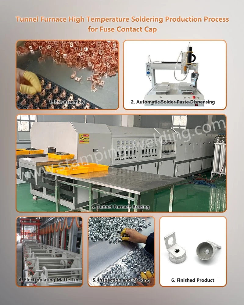
Shear Strength, Electrodynamic Forces and Thermal Stability Under Fault Conditions
Electrodynamic Loading During Short-Circuit Interruption
High fault currents produce substantial electromagnetic forces between adjacent current-carrying conductors. For two parallel conductors, a simplified force-per-unit-length relationship is:
This idealized relationship illustrates why current magnitude and conductor spacing influence mechanical loading. Actual fuse assemblies have more complex current paths, time-varying currents, magnetic interactions, and structural constraints.
A 120 kA prospective short-circuit rating must not be inserted directly into a static force calculation without considering the actual fault waveform, peak asymmetrical current, circuit power factor, and interruption behavior.
The brazed contact joint should be validated against the load cases derived from the intended fuse design.
Mechanical Strength Testing for Brazed Copper Joints
Mechanical qualification should reflect the actual joint geometry and load direction. A coupon result cannot automatically be applied to a finished contact with different thickness, overlap, or stress distribution.
| Test | Measurement | Engineering purpose |
| Lap-shear test | Maximum load and failure mode | Evaluate resistance to joint shear |
| Tensile test | Maximum load and elongation where applicable | Evaluate resistance to separation |
| Metallographic analysis | Filler penetration and interface condition | Verify joint formation |
| Thermal cycling | Resistance and structural changes after cycling | Assess degradation under repeated temperature changes |
| Current-carrying temperature-rise test | Temperature at defined operating current | Evaluate assembly thermal performance |
| Short-circuit interruption test | Fuse interruption behavior under specified conditions | Validate the complete fuse system |
Acceptance limits should be defined by the drawing, customer specification, product qualification plan, and relevant standards. A universal shear-strength threshold cannot be assigned without the joint dimensions and loading configuration.
Thermal Stability and Contact Resistance
The total resistance of a current path includes the bulk copper, the brazed interface, and the external contact interface. A four-wire measurement isolates the resistance of the specified measurement segment more reliably than a two-wire measurement.
During rated-current testing, the following parameters should be recorded:
Initial resistance at a controlled reference temperature.
Stabilized temperature rise under the specified current.
Resistance after thermal cycling.
Resistance after mechanical and electrical endurance testing.
Evidence of joint separation, discoloration, or localized overheating.
Engineering note: Short-circuit breaking capacity and continuous-current temperature rise are separate qualification parameters. The former concerns safe fault interruption by the complete fuse; the latter evaluates heating during normal operation.
Request Free DFM Evaluation & Quote
Precision Stamping and Automated Brazing for Repeatable NH Fuse Contact Production
Progressive Die Design and Copper Blade Dimensional Control
The stamping process establishes the geometry that determines brazing alignment, current-path dimensions, and final assembly fit. Burr direction, flatness, edge condition, and hole position can affect both fixture repeatability and the effective brazed interface.
Apollo's precision metal stamping process can be configured around customer-approved drawings, material specifications, and production volumes.
Key controls include:
Progressive die design for repeatable blade profiles.
Punch-to-die clearance matched to copper grade and sheet thickness.
Burr-height inspection at electrically or mechanically critical edges.
Flatness and hole-position measurement before brazing.
Fixture alignment verification during brazing trials.
A dimensional tolerance of ±0.01 mm may be appropriate for selected critical features when the part geometry, material behavior, and measurement capability support it. It should not be applied indiscriminately to every stamped feature.
Automated Brazing Process Control and Traceability
Automated or semi-automated brazing reduces operator-dependent variation when the equipment, fixture, and process parameters are qualified.
The process control plan should specify:
| Control item | Recorded or verified parameter |
| Incoming copper material | Grade, temper, thickness, and lot number |
| Joint preparation | Surface condition and cleanliness |
| Filler metal | Alloy designation, batch, and quantity |
| Brazing cycle | Temperature profile, dwell time, and atmosphere |
| Fixture condition | Alignment, clearance, and part location |
| Post-braze inspection | Joint appearance, dimensions, and applicable NDT |
| Electrical verification | Resistance and temperature-rise results, where specified |
| Traceability | Link between raw material, process batch, and inspection record |
Where required by the customer, the documentation package can include process flow, PFMEA, control plan, dimensional results, material certificates, process validation, and PPAP Level 3 submission. Delivery scope and approval timing must be agreed at project launch.
Production Qualification from Prototype to Mass Production
A controlled launch sequence separates design verification from production capability validation.
1. Prototype stage: Confirm contact geometry, filler-metal compatibility, joint clearance, and fixture concept.
2. Process-development stage: Establish the brazing window and verify representative cross-sections.
3. Qualification stage: Complete agreed mechanical, electrical, thermal, and nondestructive tests.
4. Production-validation stage: Verify dimensional repeatability, process capability, traceability, and documentation.
5. Mass-production stage: Monitor defined critical-to-quality parameters and respond to process drift through documented corrective action.
The required sample quantity, production run size, capability indices, and PPAP submission level depend on customer requirements and the program's risk classification.
NH Fuse Contact Supplier Selection: Engineering and Quality Evaluation Matrix
When evaluating an NH fuse contact brazing supplier, purchasing and engineering teams should assess more than the quoted component price. Joint-process repeatability, material traceability, inspection capability, and support for assembly qualification directly influence launch risk.
| Supplier evaluation criterion | Evidence to request | Why it matters |
| Copper stamping capability | Dimensional reports and tooling validation records | Confirms geometric consistency |
| Silver brazing capability | Qualified process parameters and sample cross-sections | Confirms joint formation |
| Defect detection | NDT procedure and reference-sample correlation | Establishes inspection reliability |
| Electrical validation | Resistance and temperature-rise test reports | Evaluates current-path performance |
| Mechanical validation | Shear or tensile results with specimen details | Confirms joint load capacity |
| Quality management | Applicable certification and audit records | Verifies management-system scope |
| Production traceability | Material and process batch records | Supports containment and root-cause analysis |
| Product qualification support | Agreed validation plan and PPAP documentation | Reduces supplier-approval uncertainty |
For high-breaking-capacity NH fuse applications, qualification should address the complete fuse assembly and its operating envelope. Component supplier data support the assessment but do not replace system-level interruption testing.
FAQ
Can an NH fuse contact brazing supplier guarantee a bonded-area ratio above 95%?
A supplier can adopt a greater-than-95% bonded-area target when the joint design, inspection method, and acceptance criteria are defined. Verification should combine validated nondestructive inspection with representative metallographic sections.
Is AWS BAg-7 suitable for silver-brazing copper NH fuse knife contacts?
AWS BAg-7 can be suitable for compatible copper joint designs because of its silver-based composition and brazing characteristics. Final selection requires verification of joint clearance, service temperature, mechanical strength, electrical resistance, and environmental requirements.
What documentation can an industrial fuse blade manufacturer provide for PPAP Level 3?
A supplier can provide an agreed PPAP Level 3 package containing dimensional results, material records, process flow, PFMEA, control plan, capability evidence where applicable, and validation reports. The exact submission scope depends on customer-specific requirements.
contact us