Metal Stamping Terminals and Current Shunt Assemblies for 12V/48V Automotive Start-Stop Batteries
Oct 24, 2026
Metal stamping terminals and current shunt assemblies for 12V and 48V automotive start-stop batteries must withstand repeated high-current cranking, electrical heating, mechanical vibration, and corrosive battery environments. Reliable production depends on controlled copper, brass, or lead-alloy forming, low-thermal-distortion joining of copper conductors to manganin resistive elements, and validation against defined electrical and mechanical acceptance criteria. Xiamen Apollo Stamping Welding Technology Co., Ltd. supports OEM development of stamped battery terminals, precision metal components, and current shunt assemblies for automotive power systems.

12V/48V Start-Stop Battery Terminals: High-Current Loading and Fatigue Requirements
Repeated Cranking Loads and Electrical Contact Stability
Automotive start-stop systems repeatedly disconnect and restart the engine during vehicle operation. Their battery terminals experience cyclic electrical loading, clamp forces, engine-bay vibration, and temperature variation. In 48V mild-hybrid systems, terminal and connection designs must also accommodate the requirements of belt starter-generators, DC/DC converters, and associated power distribution circuits.
The electrical and mechanical performance of a battery terminal depends on four interacting factors:
Contact resistance: Excessive resistance increases local Joule heating according to \(P=I^2R\).
Mechanical retention: Clamp geometry and terminal stiffness determine resistance to loosening under vibration.
Material strength: Yield strength, hardness, and work hardening influence deformation during installation and service.
Surface protection: Plating quality and substrate preparation affect corrosion resistance and long-term contact stability.
For example, at a current of 500 A, a connection resistance of 100 μΩ generates 25 W of instantaneous resistive heat. At 1,000 A, the same resistance generates 100 W. These figures illustrate why micro-ohm-level resistance control matters during high-current events; actual acceptance limits depend on the current profile, pulse duration, thermal mass, and system design.
| Engineering parameter | Potential failure mechanism | Recommended verification |
| Contact resistance | Local overheating and voltage drop | Four-wire Kelvin measurement |
| Terminal clamp force | Loosening or contact degradation | Torque and retention testing |
| Terminal cross-section | Excessive electrical resistance | Dimensional and material inspection |
| Crimp or welded interface | Joint heating or mechanical separation | Joint resistance and pull testing |
| Surface plating | Corrosion and increased contact resistance | Coating thickness and corrosion testing |
| Terminal geometry | Fatigue cracking under vibration | Dimensional inspection and vibration validation |
12V Lead-Acid and 48V Lithium Battery Interface Requirements
Lead-acid batteries commonly use lead-alloy terminal posts, while automotive lithium battery systems may use copper or copper-alloy terminals and engineered busbar interfaces. Material selection must reflect the battery chemistry, terminal architecture, fastening method, and current-carrying requirements.
A terminal designed for a conventional 12V lead-acid battery should not automatically be transferred to a 48V lithium system. Differences in conductor geometry, current distribution, connection hardware, and thermal management can require a new design-validation process.
| Design factor | 12V lead-acid battery | 48V lithium battery system |
| Typical terminal materials | Lead alloys, brass, copper | Copper, copper alloys, engineered conductive assemblies |
| Primary connection concern | Clamp integrity and corrosion | Current distribution, thermal management and joint reliability |
| Environmental exposure | Acid mist, moisture and engine-bay contaminants | Vibration, moisture, thermal cycling and electrical transients |
| Manufacturing focus | Casting, cold forming, stamping and machining | Precision stamping, joining and dimensional control |
| Validation emphasis | Contact resistance, retention and corrosion | Electrical, thermal, vibration and system-level safety |
Final material and process selection must be based on the approved component drawing and vehicle-level requirements.
Precision Forming of Lead-Alloy, Brass and Copper Battery Terminals
Material Selection for High-Current Battery Terminal Stamping
Start-Stop Battery Terminal Stamping requires a manufacturing route matched to both the material and the finished geometry. Thick terminal posts, flat conductive tabs and integrated sensor brackets may require different combinations of cold heading, precision stamping, machining and joining.
| Material | Electrical and mechanical characteristics | Suitable manufacturing applications | Key process consideration |
| Lead alloy | High density, relatively low hardness and good castability | Lead-acid battery posts and terminal structures | Control porosity, dimensional variation and creep |
| C11000 copper | High electrical conductivity, good thermal conductivity and ductility | High-current terminal plates and conductor interfaces | Control burrs, springback and deformation |
| C26800 brass | Higher strength and hardness than pure copper, with lower conductivity | Terminal clamps, connector bodies and formed hardware | Balance forming load, contact pressure and resistance |
| Copper alloy grades | Strength and spring characteristics depend on composition and temper | Stamped contact elements and sensor components | Verify conductivity and mechanical properties for the selected grade |
C11000 copper is commonly specified where low electrical resistance is a priority. C26800 brass may be preferred where stiffness, thread integrity, or clamp retention is more important than maximum conductivity. Neither material should be selected by conductivity alone.
For lead-alloy terminal posts, cold heading and casting are established process options depending on the alloy, geometry and production route. Conventional sheet-metal stamping is more appropriate for flat terminal components, mounting brackets and conductive plates.
Tooling Design and Dimensional Control for Stamped Terminals
Terminal performance can deteriorate when burrs, springback or inconsistent forming dimensions affect the mating interface. Precision tooling must therefore control the complete functional geometry rather than only the external profile.
The primary process controls include:
Die clearance: Set according to substrate thickness, alloy temper, and required edge quality.
Punch and die wear: Monitor cutting-edge degradation to limit burr growth during long production runs.
Bend radius: Prevent excessive tensile strain and cracking in formed copper-alloy components.
Flatness and parallelism: Maintain stable contact pressure across mating surfaces.
Hole position and diameter: Control fastening alignment and torque transfer.
Deburring: Prevent sharp edges from damaging insulation, adjacent wiring, or protective coatings.
For high-volume programs, progressive dies can integrate blanking, piercing, forming and other compatible operations into a repeatable production sequence. Deep sections, threaded features and complex terminal-post geometries may require separate cold-heading, machining or assembly operations.
The appropriate dimensional tolerance must be assigned according to the function of each feature. A blanket ±0.01 mm tolerance across an entire terminal is not always technically or economically justified; critical contact interfaces and sensor alignment features should receive tighter controls where the design requires them.

Process Capability and Automotive Quality Documentation
For automotive terminal programs, manufacturing capability should be demonstrated through measurable results rather than nominal machine accuracy alone.
| Quality control | Measurement or record | Purpose |
| Incoming material inspection | Alloy designation, temper, and material certificate | Confirm substrate consistency |
| First-article inspection | Critical dimensions and functional geometry | Validate die setup |
| Statistical process control | Control charts and capability studies | Detect process drift |
| CMM inspection | Three-dimensional geometry where applicable | Verify complex features |
| Electrical testing | Four-wire resistance measurement | Confirm conductor and joint performance |
| Traceability | Lot, material and production records | Support containment and corrective action |
IATF 16949 requirements, where applicable to the supplier's certified scope and customer-specific requirements, support automotive process control. PPAP Level 3 may be required by the customer to document design conformity, process capability, and production approval. Certification, submission level, and actual capability must be confirmed for the specific manufacturing site and program.
Request Free DFM Evaluation & Quote
Copper-to-Manganin Joining for Precision Battery Current Shunt Assemblies
Manganin Resistance Elements and Current Measurement Accuracy
A battery current shunt measures current through the voltage drop across a calibrated resistive element. Manganin, a copper-manganese-nickel alloy, is widely used in precision shunts because of its relatively low temperature coefficient of resistance and stable resistivity within its specified operating range.
For a nominal 100 μΩ shunt carrying 500 A, the voltage drop is 50 mV and instantaneous resistive dissipation is 25 W.
This creates a design trade-off: lower resistance reduces power dissipation but also reduces the measurable voltage signal. The resistance value must be coordinated with the current-sensing electronics, permitted voltage drop, thermal design, and calibration range.
| Shunt design parameter | Engineering significance | Verification method |
| Nominal resistance | Establishes voltage output at a given current | Four-wire resistance measurement |
| Resistance tolerance | Determines initial measurement accuracy | Calibrated low-resistance measurement |
| Temperature coefficient | Controls resistance drift with temperature | Temperature-dependent resistance testing |
| Joint resistance | Adds error and localized heating | Kelvin measurement across the assembly |
| Thermal distribution | Affects calibration stability and joint durability | Thermocouple or infrared assessment |
| Sense-terminal location | Influences parasitic voltage pickup | Layout review and repeatability testing |
The finished assembly must be calibrated as a complete electrical component. Measuring the manganin strip alone does not establish the resistance or accuracy of the assembled shunt.
Laser Welding Versus Electron Beam Welding for Copper-Manganin Joints
Joining copper conductors to manganin requires control of heat input, interface geometry, and alloy mixing. Excessive heat can alter the local resistance distribution, distort the strip, or change the electrical properties of the heat-affected region.
Laser welding and electron beam welding offer different process characteristics. Selection depends on material thickness, joint design, production volume, access, equipment configuration, and inspection requirements.
| Parameter | Laser welding | Electron beam welding |
| Energy delivery | Focused optical beam | Focused electron beam |
| Operating environment | Commonly atmospheric or shielding-gas controlled | Typically requires a vacuum chamber |
| Heat input control | Precise control through power, speed, and beam focus | High energy concentration with controlled beam parameters |
| Copper joining concern | Reflectivity and thermal conductivity can destabilize the weld | Beam-material interaction and vacuum process control |
| Production integration | Well suited to automated in-line production | Vacuum loading and cycle time affect throughput |
| Primary process risks | Porosity, lack of fusion and excessive local heating | Distortion, process sensitivity and vacuum-related throughput constraints |
Neither process automatically guarantees a low-resistance shunt. Joint qualification must demonstrate electrical stability, mechanical integrity, and acceptable resistance drift after thermal and vibration exposure.
Where joint geometry and material compatibility permit, resistance welding or other qualified joining methods may also be evaluated. The selected process should be validated against the actual copper and manganin grades rather than chosen solely by nominal welding speed.
Joint Design and Resistance Stability Under Thermal Cycling
For a Battery Current Shunt OEM project, the joining interface is part of the metrology system. A mechanically sound weld can still produce inaccurate readings if the current path or voltage-sense locations are poorly designed.
The following design controls are particularly important:
Maintain symmetrical conductor geometry to reduce unintended current-density concentration.
Position Kelvin sense points outside the primary high-current joint region where the design permits.
Control weld width, penetration, and overlap to maintain repeatable current transfer.
Prevent excessive heat exposure of the manganin resistance element.
Measure assembled resistance before and after environmental conditioning.
Inspect weld cross-sections during process qualification to evaluate fusion, porosity, and interface integrity.
For high-current designs, finite element analysis can help predict current density and temperature distribution. Simulation results should be correlated with physical resistance and thermal measurements before production release.
Corrosion Protection and ISO 16750-3 Vibration Validation for Automotive Battery Connections
Surface Finishing for Acid Mist and Engine-Bay Exposure
Battery terminals operate in environments that may include electrolyte mist, condensation, road salt, cleaning chemicals, and elevated temperatures. Corrosion products increase interface resistance and can compromise fastening integrity.
Surface protection must be selected according to the substrate, electrical function, and environmental exposure.
| Surface treatment | Typical purpose | Engineering considerations |
| Tin plating | Improve solderability and provide a conductive protective surface | Control thickness, porosity and intermetallic growth |
| Silver plating | Support low-resistance contact interfaces in suitable applications | Evaluate tarnish, wear and compatibility with mating materials |
| Nickel plating | Provide a diffusion barrier and corrosion-resistant surface | Account for contact resistance and coating hardness |
| Copper plating | Provide a conductive intermediate layer | Control adhesion and subsequent coating compatibility |
| Unplated copper | Avoid coating cost and additional process steps | Requires appropriate environmental protection and interface design |
Plating thickness should be specified on the engineering drawing and verified using a suitable method, such as X-ray fluorescence (XRF).
Adhesion, porosity and corrosion performance should be assessed according to the applicable coating specification and customer requirements.
For lead-acid battery interfaces, corrosion testing should reflect the expected exposure to electrolyte vapour and moisture. A generic salt-spray result alone does not establish resistance to every battery-specific corrosive environment.
Vehicle Vibration and Mechanical Fatigue Testing
ISO 16750-3 addresses mechanical loads for electrical and electronic equipment in road vehicles. The applicable vibration profile depends on component location, mounting method, and the vehicle manufacturer's requirements.
Battery terminals and current shunt assemblies should be assessed for:
Mechanical loosening at fasteners and clamps
Fatigue cracking near stamped bends or welded joints
Intermittent electrical connections
Resistance drift after vibration
Sensor output instability caused by mechanical strain
Insulation damage caused by movement against adjacent components
A useful validation sequence includes baseline electrical measurement, mechanical vibration exposure, post-test dimensional inspection, and repeat electrical measurement. Where required, resistance should also be monitored during vibration to identify intermittent faults that may not remain visible after testing.
The test profile, frequency range, acceleration, duration, and mounting orientation must be specified by the applicable OEM requirement. There is no single ISO 16750-3 vibration setting that is valid for every battery terminal or shunt.
Validation Matrix for 12V/48V Terminal and Shunt Assemblies
| Test | Main failure mode assessed | Acceptance basis |
| Four-wire resistance | Excessive resistance and drift | Component drawing and electrical specification |
| Temperature-rise test | Local overheating | Maximum permitted temperature under defined current loading |
| Mechanical retention test | Clamp slip or joint separation | Specified torque, force and displacement limits |
| ISO 16750-3 vibration | Fatigue and intermittent contact | Applicable vehicle mounting category and OEM profile |
| Corrosion exposure | Coating degradation and resistance increase | Approved environmental specification |
| Thermal cycling | Differential expansion and joint degradation | Defined temperature range and cycle count |
| Weld cross-section inspection | Lack of fusion or excessive penetration variation | Qualified weld acceptance criteria |
| Calibration verification | Current measurement error | Shunt accuracy class and customer specification |
Request Free DFM Evaluation & Quote
OEM Manufacturing Workflow for Automotive Battery Terminals and Current Shunts
From Drawing Review to Production Approval
A controlled OEM program begins with a drawing and specification review. The manufacturing process must reflect the electrical function of the part, not merely its external dimensions.
Apollo's engineering review for suitable stamped and welded components can address:
1. Drawing and material review: Confirm alloy, temper, thickness, plating, geometric tolerances, and electrical requirements.
2. DFM assessment: Identify forming risks, burr-sensitive interfaces, difficult weld access, and inspection limitations.
3. Tooling development: Define blanking, piercing, forming, and any secondary operations.
4. Joining development: Establish qualified laser or electron beam welding parameters where the design requires them.
5. Prototype verification: Measure dimensions, resistance, joint integrity, and other specified characteristics.
6. Production validation: Confirm process repeatability and inspection methods before volume release.
7. Documentation: Prepare inspection records, material traceability, and customer-required PPAP documentation where agreed.
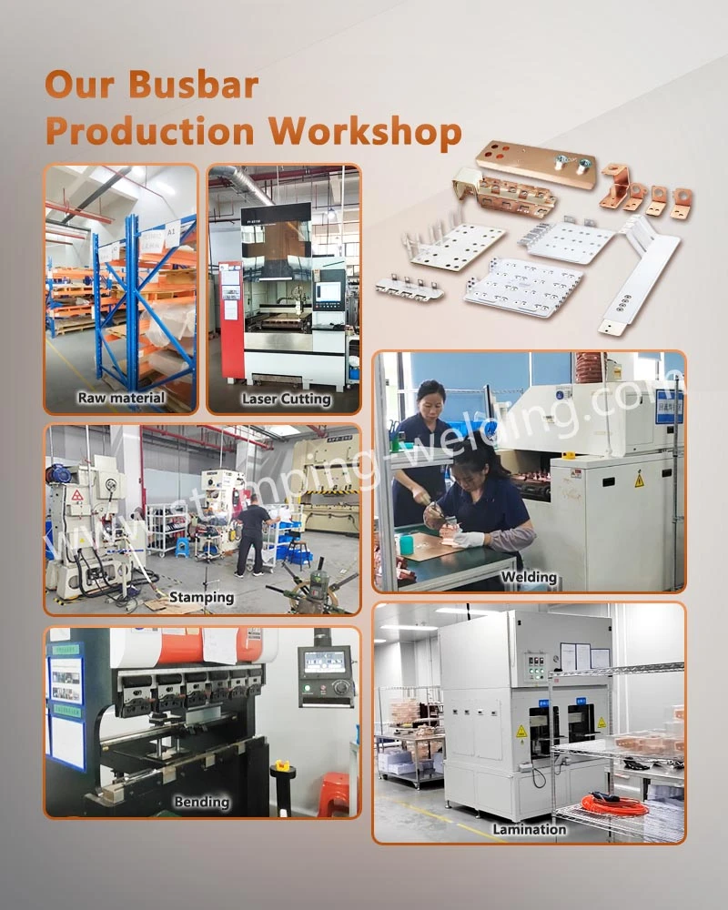
A complete production route may combine precision stamping, cold forming, machining, surface treatment, welding and assembly. The exact process sequence depends on the part drawing and annual volume.
Quality Planning and Traceability for PPAP Level 3
PPAP Level 3 submissions typically require a defined package of production-part approval evidence under the applicable AIAG manual and customer-specific requirements. The precise submission contents must be agreed with the customer; no single checklist replaces customer approval requirements.
Typical records may include:
Design records and approved engineering changes
Process flow diagram and process FMEA
Control plan and dimensional results
Material and performance test results
Measurement system analysis where applicable
Initial process studies for designated characteristics
Appearance approval or other customer-specific records
Part Submission Warrant
For current shunts, traceability should link the resistance calibration result to the corresponding part or production lot, according to the required traceability level. For stamped terminals, critical material lots, plating batches and tooling revisions should be identifiable when specified by the control plan.
Supplier capability should be verified against the actual manufacturing location, product scope, and customer requirements. ISO 9001 or IATF 16949 certification should only be claimed where valid certification documentation supports the statement.
Selecting an OEM Partner for Lead-Acid to Lithium Battery Connectors
Engineering Review Criteria for Cross-Chemistry Battery Interfaces
Lead-Acid to Lithium Battery Connectors must account for differences in terminal materials, electrical architecture, fastening interfaces, and environmental conditions. Reusing an existing terminal design without checking the new application can introduce unacceptable heating, corrosion, or mechanical retention risks.
| Supplier evaluation item | Evidence to request | Why it matters |
| Material control | Certificates and incoming inspection records | Confirms alloy and temper |
| Stamping capability | Tooling layout and dimensional reports | Establishes forming repeatability |
| Welding capability | Qualified procedure and joint inspection records | Demonstrates interface consistency |
| Electrical measurement | Four-wire resistance and calibration records | Verifies low-resistance performance |
| Surface finishing | Plating specification and thickness reports | Controls corrosion and contact behavior |
| Automotive quality | Valid certification and customer approval records | Establishes the applicable quality framework |
| Production readiness | Capacity plan and process validation results | Supports volume planning |
| Engineering change control | Revision and traceability records | Prevents unauthorized process or material changes |
Apollo's Manufacturing Scope for Stamped Electrical Components
Xiamen Apollo Stamping Welding Technology Co., Ltd. focuses on precision metal stamping and welding components for automotive electrical systems, EV applications, energy storage, and power electronics.
For battery terminal and current shunt development, the relevant manufacturing operations may include precision stamping, forming, joining, dimensional inspection, and component assembly, subject to the approved design and validated production route.
The principal engineering objective is repeatability across the complete part: material properties, contact geometry, joining quality, electrical resistance, and environmental durability. These characteristics should be defined as measurable acceptance criteria before tooling release and mass production.
FAQ: Automotive Battery Terminal Stamping and Current Shunt OEM
1. What information is required to request a quote for start-stop battery terminal stamping?
Provide the 2D drawing or 3D model, material and temper, thickness, surface finish, critical tolerances, annual volume, and applicable validation requirements. Include the battery voltage, current profile, and terminal interface specification where available.
2. How is resistance accuracy verified for a copper-manganin battery current shunt?
Use calibrated four-wire Kelvin measurement on the assembled shunt under controlled temperature conditions. Verify nominal resistance, tolerance, and temperature-related drift against the drawing, then repeat measurements after required thermal and vibration tests.
3. Which tests are required for automotive battery terminals under ISO 16750-3?
ISO 16750-3 mechanical testing should use the vibration profile applicable to the component's mounting location and vehicle requirements. The validation plan should also define electrical continuity, post-test resistance, mechanical integrity, and inspection acceptance criteria.
contact us