In-Die Tapping and Threaded Bushing Insertion in High-Volume Electrical Sheet Metal Stamping
Oct 31, 2026
In-die tapping integrates thread formation directly into a progressive stamping line, reducing the handling, labor, and positioning errors associated with offline machining. For electrical sheet metal components requiring M3–M10 threads, a servo-driven tapping unit can synchronize with the press cycle at speeds of up to 150 strokes per minute, subject to thread pitch, material thickness, and tooling configuration. Thread quality depends on tap alignment, pilot-hole accuracy, lubrication, chip evacuation, and in-process inspection-not press speed alone.
Why In-Die Tapping Reduces Secondary Machining Risks in High-Volume Production
Conventional sheet metal stamping often produces threaded components through a separate machining operation. After blanking and forming, parts are transferred to tapping stations, where operators or automated equipment drill and cut threads.
This additional production stage creates several sources of variation:
Positioning deviation: Repeated clamping can shift the tapping datum relative to the stamped profile.
Thread-axis misalignment: Poor fixture support or workpiece deformation can produce angular deviation between the thread axis and the mounting surface.
Incomplete threading: Incorrect feed depth, worn taps, or chip accumulation can leave insufficient usable thread engagement.
Thread damage: Manual handling and uncontrolled tool withdrawal can damage thread crests or produce cross-threading.
Production traceability gaps: Separate machining stations can complicate lot-level process monitoring and defect containment.
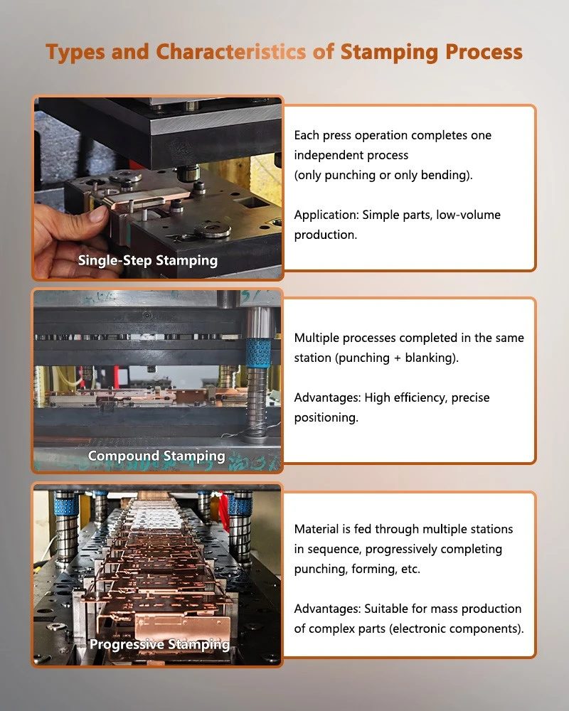
Integrating tapping into a progressive die reduces the number of transfers between operations. The stamped component remains located by the die's guiding and positioning system while the tapping mechanism performs thread cutting at a defined station.
Offline Tapping vs. Progressive Die Tapping: Process Comparison
| Evaluation factor | Offline tapping | In-die tapping |
| Workpiece positioning | Separate fixture required | Referenced to progressive die positioning |
| Production handling | Additional transfer and loading | Integrated into stamping sequence |
| Thread-axis consistency | Depends on fixture and operator setup | Depends on die guidance and tapping-unit alignment |
| Cycle synchronization | Separate machining cycle | Synchronized with press operation |
| Chip management | Managed at standalone station | Requires dedicated chip evacuation |
| Process monitoring | Separate machining records | Can be integrated into stamping inspection records |
| Production suitability | Flexible for low-volume work | Suitable for stable, high-volume programs |
The principal benefit is process integration. However, in-die tapping is not automatically suitable for every stamped component. Parts with insufficient tapping clearance, unstable pilot-hole geometry, or difficult chip evacuation may require a separate machining operation.
Pilot-Hole Accuracy and Thread Engagement Control
Thread quality starts before the tap enters the material. The pilot hole must be designed according to the selected thread specification, material grade, thread engagement length, and tapping method.
For metric ISO threads, the nominal tap-drill diameter is commonly estimated using:
This relationship is a preliminary sizing reference, not a substitute for a validated tooling specification. Actual pilot-hole dimensions must account for material behavior, required thread percentage, coating, and applicable thread tolerances.
For thin electrical sheet metal, engineers should also evaluate whether the available material thickness provides sufficient thread engagement. Where direct tapping cannot provide the required pull-out or torque performance, a threaded bushing or other reinforced fastening structure may be more appropriate.
Material and Geometry Factors in M3–M10 Tapping
| Material or component | Main tapping consideration | Engineering control |
| Low-carbon steel sheet | Burr formation and tap wear | Pilot-hole deburring and tool-life monitoring |
| Stainless steel sheet | Work hardening and heat generation | Appropriate tap geometry, speed, and lubrication |
| Aluminum alloy sheet | Adhesion and chip packing | Suitable coating, lubrication, and chip evacuation |
| Copper components | Material ductility and thread deformation | Controlled cutting conditions and thread inspection |
| Formed brackets | Local distortion and access clearance | Die support and tapping-station positioning |
Request a Stamping DFM Evaluation
Servo-Driven Tapping Mechanisms Inside Progressive Dies
In-die tapping requires the rotational movement of the tap to remain synchronized with its axial feed. Unlike conventional press-driven punching, thread cutting involves a defined relationship between spindle rotation and vertical travel.
A servo-driven tapping mechanism provides programmable control of spindle rotation, feed depth, reversal, and withdrawal. Its motion profile must match the press cycle and the thread geometry.
Operating Sequence of a Servo Tapping Unit
A typical progressive die tapping station follows this sequence:
1. Strip feeding and positioning: The material strip advances through the progressive die and reaches the tapping station.
2. Pilot-hole verification: The previously formed hole is positioned relative to the tapping spindle.
3. Die support and clamping: The component is stabilized to limit vibration and local deformation during cutting.
4. Synchronized spindle movement: The servo system rotates the tap while controlling its axial feed according to the specified thread pitch.
5. Thread-depth control: The tapping unit reaches the programmed depth without exceeding the available material thickness or specified engagement length.
6. Reverse rotation and withdrawal: The spindle reverses to remove the tap while minimizing thread damage.
7. Chip evacuation: Cutting chips are removed from the tapping area to prevent interference with subsequent die operations.
8. Strip advancement: The press cycle continues after the tapping mechanism returns to its safe position.
The spindle feed must correspond to the thread pitch. For a single-start metric thread, the theoretical axial feed per revolution equals the thread pitch.
This synchronization is essential. A mismatch between rotational speed and axial feed can cause thread tearing, tap overload, or premature tool failure.
M3–M10 Thread Range and 150 SPM Press Synchronization
A servo tapping system can be configured for M3–M10 applications, depending on material thickness, tap diameter, thread pitch, die layout, and available operating time within each press cycle.
This 0.4-second interval is the nominal press-cycle duration, not necessarily the available tapping time. The tapping unit must complete its cutting, reversal, and withdrawal sequence within the permitted motion window.
| Parameter | Engineering significance | Validation requirement |
| Thread size | Determines tap diameter and cutting load | M3–M10 drawing specification |
| Thread pitch | Defines axial feed per revolution | ISO metric thread requirement |
| Press speed | Determines available cycle time | Confirmed press operating profile |
| Spindle speed | Influences cutting time and tool loading | Material and tap manufacturer recommendations |
| Tapping depth | Determines effective thread engagement | Drawing and fastening design |
| Pilot-hole diameter | Controls thread formation and cutting torque | Validated tooling dimension |
| Lubrication | Affects friction, heat, and chip removal | Material-specific process validation |
The stated 150 SPM represents a potential press synchronization target, not a universal guaranteed output for every M3–M10 thread. Larger thread sizes, deeper engagement, and difficult-to-machine materials may require a reduced press speed.
Tap Selection, Lubrication, and Chip Evacuation
Tap selection must consider the material, thread geometry, hole configuration, and tapping depth.
For blind holes, chip accumulation can obstruct the tap and reduce effective thread depth. Through-holes provide a different chip-discharge path but still require control of chip contamination within the die.
Key process controls include:
Tap geometry matched to the workpiece material.
Controlled spindle torque to identify abnormal cutting resistance.
Lubrication compatible with the material and downstream surface treatment.
Defined tap replacement criteria based on tool life and inspection results.
Chip removal that prevents metal fragments from entering die-clearance areas.
Interlocks that stop the process when tap breakage or abnormal spindle loading is detected.
Threaded Bushing Insertion and Reinforced Fastening Structures
Direct tapping is not always suitable for thin-gauge electrical sheet metal. When the available sheet thickness cannot provide sufficient thread engagement, a threaded bushing can provide a more suitable fastening interface.
A threaded bushing is a separate metal insert installed into a prepared hole or formed mounting feature. Depending on the design, it may be mechanically clinched, press-fitted, staked, or secured through another validated joining process.
The selection depends on the required fastening load, material thickness, installation access, vibration exposure, and assembly sequence.
Direct Sheet-Metal Tapping vs. Threaded Bushing Insertion
| Design factor | Direct in-die tapping | Threaded bushing insertion |
| Base material thickness | Requires adequate thread engagement | Can accommodate thinner sheet designs |
| Part count | No separate insert | Requires an additional component |
| Installation process | Thread cutting | Insert feeding and mechanical installation |
| Pull-out resistance | Depends on thread engagement and sheet strength | Depends on insert geometry and retention method |
| Torque resistance | Limited by thread and base-material strength | Depends on insert retention and surrounding material |
| Cost structure | Tap tooling, maintenance, and machining time | Insert cost, feeding equipment, and insertion tooling |
| Typical application | Sheet-metal mounting holes | Reinforced threaded fastening points |
Bushing insertion should not be specified solely to increase nominal thread strength. The surrounding sheet material must also withstand installation forces and service loads without cracking, distortion, or local pull-through.
Bushing Insertion Variables for Progressive Die Production
The insertion station must control the relationship between the bushing, receiving hole, and supporting die structure.
Important variables include:
Receiving-hole geometry: Hole diameter, roundness, and burr condition affect insertion consistency.
Insert orientation: The bushing must enter the receiving feature in the correct direction.
Insertion force: Excessive force may deform the sheet or damage the insert; insufficient force may result in weak retention.
Support geometry: The lower die must provide adequate support around the insertion point.
Final height: Protrusion or flushness must match the assembly drawing.
Rotational retention: The installed insert must resist the specified fastening torque without spinning.
Pull-out resistance: Axial retention must meet the component's mechanical requirements.
For automated production, the insert-feeding system should also detect missing, inverted, or incorrectly positioned bushings before the part exits the die.
In-Die Tapping and Bushing Insertion: Process Selection Matrix
| Design requirement | Preferred process direction |
| Adequate sheet thickness and moderate fastening load | Direct in-die tapping |
| Thin sheet with higher fastening load | Threaded bushing insertion |
| High-volume production with stable thread geometry | Progressive die tapping |
| Repeated assembly and disassembly | Evaluate reinforced threaded insert |
| Restricted access to the rear surface | Evaluate one-sided installation methods |
| High vibration exposure | Validate anti-rotation and retention performance |
| Mixed material construction | Evaluate galvanic corrosion and thermal expansion |
The final selection should be based on fastening torque, axial pull-out force, fatigue exposure, and assembly requirements rather than nominal thread size alone.
Online Thread Inspection and Mechanical Validation
A thread that appears visually acceptable may still fail during assembly. Typical defects include incomplete thread profiles, oversized pitch diameters, damaged thread crests, excessive burrs, and angular deviation.
For high-volume stamping, inspection should combine in-process detection with periodic dimensional and destructive testing.
Go/No-Go Gauge Inspection for M3–M10 Threads
Thread plug gauges provide a practical method for checking internal thread acceptance.
GO gauge: Verifies whether the thread can accept the specified functional gauge under the applicable inspection method.
NO-GO gauge: Checks whether the thread exceeds the permitted dimensional limit.
Inspection frequency: Defined by the control plan, production risk, and process capability.
Gauge management: Requires calibration status, identification, and controlled replacement.
Gauge inspection does not replace full thread measurement where pitch diameter, thread profile, or positional accuracy requires more detailed verification.
For critical electrical components, the inspection plan should specify the applicable thread standard, tolerance class, gauge specification, and acceptance criteria. ISO metric thread requirements should be confirmed against the current drawing and relevant ISO 965 provisions.
Torque and Pull-Out Testing for Threaded Connections
Threaded electrical components may experience repeated tightening, vibration, thermal cycling, and mechanical loading. Their acceptance criteria must reflect the actual assembly conditions.
| Test | Primary purpose | Typical failure indication |
| GO/NO-GO gauge test | Functional thread acceptance | Gauge rejection |
| Fastening torque test | Evaluate thread and joint torque behavior | Thread stripping or rotation |
| Insert pull-out test | Measure axial retention | Insert extraction or sheet pull-through |
| Anti-rotation test | Verify insert resistance to spinning | Bushing rotation |
| Thread-depth measurement | Confirm usable engagement | Insufficient thread depth |
| Visual inspection | Detect burrs and visible damage | Cracks, deformation, incomplete threads |
Test values should be established from the component drawing, customer specification, fastener grade, and joint design. A single torque value cannot be applied universally to all M3–M10 stamped components.
Online Detection and Process Interlocks
Online monitoring can reduce the risk of producing large quantities of defective threaded parts before a problem is detected.
A suitable control architecture may include:
Servo spindle torque monitoring.
Tap breakage detection.
Tapping depth and position monitoring.
Missing-part and strip-position detection.
Bushing presence and orientation detection.
Abnormal insertion-force monitoring.
Automatic machine stop or part segregation when defined limits are exceeded.
These systems provide process signals rather than automatic proof of finished-thread conformity. Periodic gauge inspection and mechanical validation remain necessary.
IATF 16949 and PPAP Level 3 Documentation
For automotive and electrical equipment supply chains, the tapping process should be supported by controlled production documentation.
A customer-specific PPAP Level 3 submission may include:
| Documentation | Relevance to tapping and bushing insertion |
| Process Flow Diagram | Defines stamping, tapping, insertion, and inspection sequence |
| PFMEA | Identifies tap breakage, incomplete threads, misalignment, and insert retention risks |
| Control Plan | Defines inspection methods, frequencies, and reaction plans |
| Dimensional Results | Records thread location, hole dimensions, and component geometry |
| Material Certification | Confirms base material and insert material requirements |
| MSA | Evaluates measurement-system suitability |
| Process Capability Study | Assesses stability of critical dimensions where applicable |
| Functional Test Results | Documents torque, pull-out, or other customer-specified validation |
PPAP Level 3 is a customer submission requirement, not an automatic consequence of using an in-die tapping process. Submission scope and approval criteria must be agreed with the customer.
Request Threaded Stamping Process Review
Electrical Enclosure and Power Distribution Applications
In-die tapping and threaded bushing insertion are suitable for electrical components where threaded mounting points must be integrated into stamped metal structures.
The process is particularly relevant to ESS enclosures, inverter assemblies, and busbar mounting structures. Each application has different mechanical, electrical, and environmental requirements.
ESS Cabinet Brackets and Structural Mounting Plates
Energy storage cabinets contain mounting brackets, equipment supports, grounding structures, and internal sheet-metal frames. These components require stable mounting geometry for electrical equipment and enclosure assembly.
Typical design considerations include:
Threaded mounting points for circuit breakers, terminal blocks, and internal supports.
Hole-position consistency relative to cabinet assembly datums.
Resistance to loosening under transport and operational vibration.
Corrosion protection compatible with the cabinet's coating system.
Adequate thread engagement for specified fastener loads.
Where the bracket uses a thin sheet-metal section, threaded bushings may be considered instead of direct tapping. The design should account for the insertion footprint and its influence on surrounding bends or formed features.
Inverter Grounding Terminal Plates
Grounding terminal plates require reliable mechanical fastening and a defined electrical contact interface.
For copper or steel grounding components, engineers should distinguish between the mechanical performance of the thread and the electrical performance of the contact surface.
| Design parameter | Engineering consideration |
| Thread size | Matches the grounding fastener and assembly specification |
| Contact surface | Controls the electrical interface between mating components |
| Surface treatment | Must not compromise the specified grounding interface |
| Fastening torque | Must maintain joint integrity without damaging the thread |
| Corrosion protection | Must account for the electrical contact area |
| Joint verification | May include resistance and mechanical testing |
A painted or powder-coated surface should not be assumed to provide a suitable conductive interface. Masking, localized coating removal, conductive plating, or a defined contact design may be required.
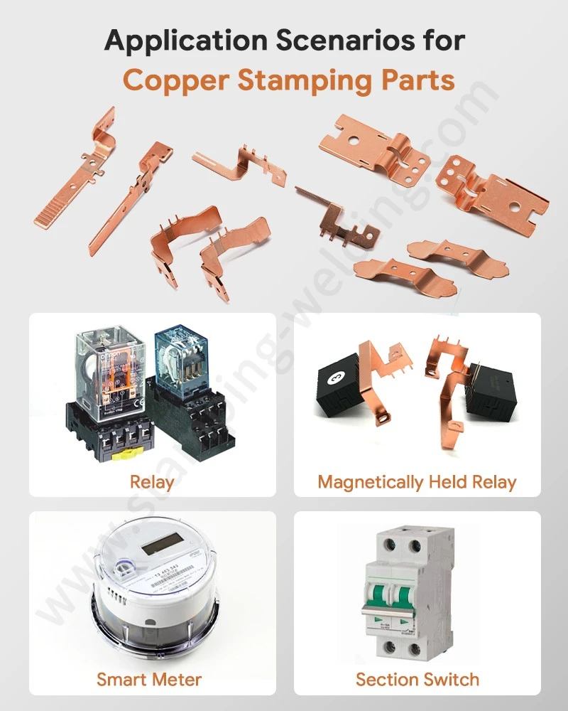
Copper Busbar Mounting Holes and Electrical Connection Points
Copper busbars used in power distribution systems often require threaded or clearance holes for terminal connections, support brackets, and enclosure mounting.
For copper components, tapping conditions must account for the material's ductility and tendency to adhere to cutting tools. Burr control is particularly important around electrical contact surfaces because raised edges can affect assembly seating and local contact pressure.
Where the design requires high-current electrical performance, the engineering review should include:
Copper grade and conductivity requirements.
Hole position and edge distance.
Contact-surface flatness.
Fastener torque and joint pressure.
Surface plating and coating thickness.
Thermal performance under the specified current load.
Thread formation alone does not establish the electrical reliability of a bolted busbar joint. Contact resistance and temperature-rise testing should be specified according to the assembly's electrical requirements.
Manufacturing Cost Control Through Integrated Die Operations
The economic value of in-die tapping comes from reducing separate handling and machining stages while maintaining the required thread quality.
However, total manufacturing cost must include the tapping unit, tap replacement, lubrication, chip management, inspection, and progressive die maintenance.
Cost Structure: Offline Machining vs. In-Die Tapping
| Cost element | Offline tapping | In-die tapping |
| Secondary machine investment | Separate tapping equipment | Integrated servo tapping unit |
| Workpiece handling | Additional loading and transfer | Reduced intermediate handling |
| Fixture requirements | Separate tapping fixture | Die-based positioning and support |
| Tooling maintenance | Standalone tap and fixture maintenance | Tap, servo unit, and die maintenance |
| Chip management | Separate machining area | Integrated die-area management |
| Inspection | Separate station or sampling | Can be incorporated into the stamping control plan |
| Production planning | Multiple process stages | More integrated production sequence |
The cost advantage depends on production volume, thread count per part, cycle time, tool life, and the complexity of the die. For low-volume products with frequent engineering changes, offline tapping may remain more economical.
DFM Review Before Progressive Die Tooling
Before finalizing the die layout, the engineering team should evaluate the following design points:
1. Thread location: Confirm sufficient clearance from bends, edges, and adjacent features.
2. Material thickness: Determine whether direct tapping can achieve the required thread engagement.
3. Hole geometry: Confirm pilot-hole diameter, burr direction, and positional tolerance.
4. Tool access: Verify spindle clearance and tap replacement access.
5. Chip evacuation: Prevent chips from accumulating in the die or contaminating electrical contact areas.
6. Press synchronization: Confirm the tapping motion fits within the available press-cycle window.
7. Inspection access: Define how gauges and functional test equipment will access the finished thread.
8. Maintenance planning: Establish tap replacement, die cleaning, and preventive maintenance intervals.
Early DFM review can prevent costly changes after progressive die manufacture. It also helps determine whether tapping, bushing insertion, or a hybrid process is appropriate for each fastening point.
Apollo's Process Integration and Quality Control
Xiamen Apollo Stamping Welding Technology Co., Ltd. applies precision stamping and integrated manufacturing methods to electrical and structural metal components.
For threaded sheet-metal parts, process planning should connect progressive die design, pilot-hole formation, tapping or bushing insertion, and final inspection into one controlled manufacturing sequence.
Production engineering should define measurable acceptance criteria for:
Thread size and tolerance class.
Thread position relative to functional datums.
Thread depth and engagement length.
Bushing insertion height and retention.
Fastening torque and pull-out performance.
Burr condition and surface integrity.
Batch traceability and inspection records.
The production route should be selected according to the component drawing, annual demand, material properties, and customer validation requirements. For automotive programs, applicable IATF 16949 quality controls and customer-specific PPAP requirements should be incorporated into the project plan.
Engineering Specification Checklist for In-Die Tapping OEM Projects
To assess whether a component is suitable for integrated tapping or threaded bushing insertion, the initial technical review should include the following information.
| Input required | Why it matters |
| 2D engineering drawing | Defines dimensions, thread callouts, and tolerances |
| 3D CAD model | Allows die layout and tapping access assessment |
| Base material and thickness | Determines cutting behavior and thread engagement |
| Thread specification | Defines diameter, pitch, tolerance class, and depth |
| Annual production volume | Supports process and tooling cost comparison |
| Fastener specification | Establishes assembly and torque requirements |
| Mechanical load requirements | Determines whether direct tapping is sufficient |
| Surface treatment | Identifies coating or plating effects on thread fit |
| Inspection requirements | Defines gauges, dimensional checks, and functional tests |
| PPAP requirements | Establishes customer documentation and approval scope |
A technically complete quotation should identify the proposed process route, tooling assumptions, inspection plan, and any design features requiring customer confirmation.
Frequently Asked Questions
1. Can progressive die tapping produce M3 to M10 threads at 150 SPM?
A servo-driven tapping unit can be designed for M3–M10 threads and synchronized with a press operating at up to 150 SPM. Actual production speed depends on thread pitch, material, tapping depth, and available cycle time.
2. When should a threaded bushing be used instead of direct in-die tapping?
Use a threaded bushing when sheet thickness cannot provide sufficient thread engagement or when the fastening design requires additional retention strength. Validate insertion force, pull-out resistance, and anti-rotation performance.
3. What inspection methods verify the quality of in-die tapped threads?
Use calibrated GO/NO-GO thread gauges for functional acceptance. Supplement them with dimensional checks, fastening torque tests, and destructive pull-out testing where required by the component specification and customer control plan.
contact us