314Ah & 587Ah Prismatic Energy Storage Cell Busbars: Integrated Thermal Runaway Venting & Overcurrent Capacity
Nov 08, 2026
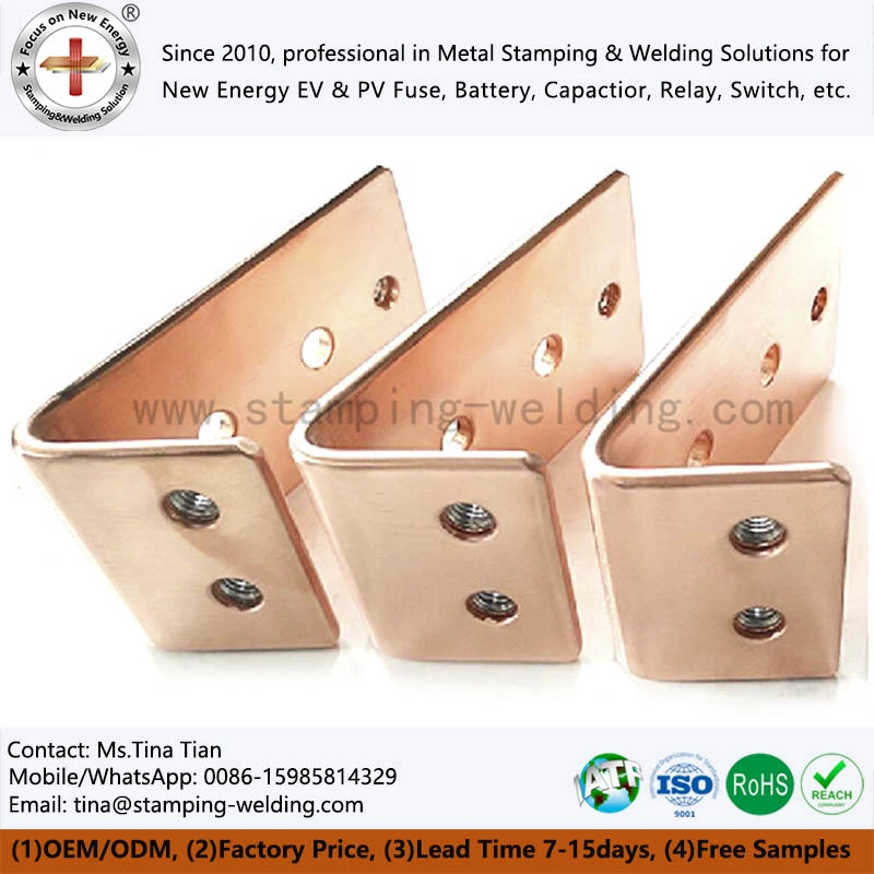
Large-format 314Ah and 587Ah prismatic energy storage cells require busbar systems designed around continuous current, terminal temperature rise, mechanical expansion, and thermal runaway vent clearance. For applications targeting 300–600A continuous current, copper busbars with a nominal thickness of 3–5 mm can provide the required conductive cross-section when width, joint resistance, and cooling conditions are correctly calculated. The busbar geometry must also preserve the cell's pressure-relief path and accommodate dimensional changes during repeated charge and discharge cycles.
Electrical Design Challenges of 314Ah and 587Ah ESS Cells
The transition to 314Ah and 587Ah prismatic cells changes the electrical and mechanical requirements of battery module interconnects.
Larger cell capacity does not automatically determine the required busbar cross-section. The actual design depends on the cell configuration, series-parallel architecture, operating current, duty cycle, ambient temperature, and thermal management system.
For a 1C operating condition, a 314Ah cell corresponds to a nominal current of 314A, while a 587Ah cell corresponds to 587A. These values represent the current associated with the stated C-rate; actual continuous and peak current limits must follow the cell manufacturer's specifications.
Current requirements at 1C operating conditions
| Cell capacity | Current at 0.5C | Current at 1C | Current at 1.5C |
| 314Ah | 157A | 314A | 471A |
| 587Ah | 293.5A | 587A | 880.5A |
A busbar designed for a 314Ah cell cannot automatically be reused for a 587Ah cell. Even where both applications use the same nominal voltage, the larger cell may require a different conductive cross-section, joint configuration, and thermal design.
The engineering review should distinguish three current conditions:
Continuous current: The current sustained during normal charging or discharging.
Peak current: A short-duration current associated with transient operating conditions.
Fault current: The prospective current during a short circuit or other electrical fault.
These conditions require different verification methods. Continuous current determines steady-state temperature rise, while peak and fault current influence electrodynamic loading, joint integrity, and protection-system coordination.
Illustrative 3–5 mm copper busbar sizing matrix
The following examples show the relationship between cross-section and average current density. They are not certified ampacity ratings.
| Copper width | Thickness | Cross-section | At 300A | At 500A | At 600A |
| 30 mm | 3 mm | 90 mm² | 3.33 A/mm² | 5.56 A/mm² | 6.67 A/mm² |
| 40 mm | 4 mm | 160 mm² | 1.88 A/mm² | 3.13 A/mm² | 3.75 A/mm² |
| 40 mm | 5 mm | 200 mm² | 1.50 A/mm² | 2.50 A/mm² | 3.00 A/mm² |
| 50 mm | 5 mm | 250 mm² | 1.20 A/mm² | 2.00 A/mm² | 2.40 A/mm² |
| 60 mm | 5 mm | 300 mm² | 1.00 A/mm² | 1.67 A/mm² | 2.00 A/mm² |
The final section should be validated by thermal analysis and current-carrying tests under representative installation conditions. A design target such as ΔT < 30K should be treated as a project-specific acceptance criterion, not a universal requirement for every ESS busbar.
Copper material selection: C1100 versus alternative conductors
C1100 oxygen-free or high-conductivity copper is commonly selected for high-current electrical connections where conductivity and forming performance are required. Other copper grades may be considered according to availability, mechanical requirements, and customer specifications.
| Material | Electrical characteristics | Mechanical considerations | Typical design consideration |
| C1100 copper | High electrical conductivity; commonly specified against IACS reference | Good formability in suitable tempers | High-current battery busbars |
| C1020 copper | High conductivity and low oxygen content | Material condition affects forming and joining | Applications with specific material requirements |
| C2680 brass | Lower conductivity than pure copper | Higher strength and different forming behavior | Structural or terminal features where conductivity is secondary |
| Aluminum 1060 | Lower conductivity than copper by volume | Lower density; different joining and oxidation behavior | Weight-sensitive electrical connections |
For a copper busbar design, the material certificate should identify the exact grade, temper, thickness and conductivity requirement. If the specification calls for 100% IACS conductivity, the measurement method and acceptance conditions should be defined.
Thermal Management and Terminal Temperature Rise Control
The temperature rise of an ESS busbar is determined by electrical losses and heat dissipation. A busbar with sufficient cross-sectional area can still experience excessive local heating if the terminal interface has high resistance or the cooling conditions are restricted.
Factors affecting ΔT < 30K performance
A project targeting a temperature rise below 30K should evaluate the following variables:
| Design variable | Thermal effect | Engineering control |
| Copper cross-section | Determines bulk electrical resistance | Optimize width and thickness |
| Busbar length | Influences total conductor resistance | Minimize unnecessary current path length |
| Terminal contact area | Affects interface resistance and heat distribution | Defines contact geometry and surface condition |
| Bolt preload | Influences electrical contact resistance | Specify fastening torque and joint design |
| Surface oxidation | Can increase interface resistance | Select suitable plating or surface treatment |
| Insulation coverage | Influences heat dissipation | Evaluate coating thickness and coverage |
| Enclosure airflow | Affects convective cooling | Validate installation airflow |
| Ambient temperature | Changes operating temperature margin | Test at specified environmental conditions |
Temperature-rise validation under representative conditions
A valid temperature-rise test should reproduce the intended electrical and mechanical installation as closely as practical.
The test plan should define:
Continuous test current and stabilization period.
Ambient temperature and airflow conditions.
Busbar orientation and mounting arrangement.
Terminal bolt torque and contact interface preparation.
Thermocouple or temperature sensor positions.
Temperature measurement uncertainty.
Acceptance limits for the busbar and terminal regions.
A four-wire Kelvin measurement can be used to measure low-resistance electrical interfaces. Infrared thermography can identify local hot spots, but emissivity differences between bare copper, plated surfaces, and insulation must be considered.
Request 314Ah / 587Ah Busbar DFM Review
Thermal Runaway Vent Clearance and 3D Busbar Geometry
Prismatic cells commonly incorporate a pressure-relief mechanism on the upper surface. During an internal fault, the safety vent releases high-temperature gases and potentially ejects particles or electrolyte-containing aerosols.
The busbar layout must not obstruct the designated vent area. A conductive component positioned too close to the vent path may be exposed to hot gas, mechanical impact, or conductive contamination.
Why busbar geometry must preserve the vent path
During thermal runaway, the venting direction and discharge characteristics depend on cell design and the pressure-relief mechanism. The released gas may contain combustible components and can reach temperatures that damage nearby insulation or structural materials.
If a copper busbar crosses the vent path, several hazards may arise:
Direct exposure to high-temperature gas.
Thermal damage to insulation or protective coatings.
Mechanical deformation from vent discharge.
Conductive contamination across adjacent terminals.
Electrical arcing if conductive debris bridges energized components.
Unintended contact between displaced busbar sections and nearby structures.
A safe layout must be based on the cell manufacturer's vent location, vent opening geometry, discharge direction, and specified keep-out region. There is no universal vent clearance dimension applicable to all 314Ah or 587Ah cells.
3D stamped busbar routing around prismatic cell vents
A flat copper strip may not provide sufficient clearance in a compact module. Three-dimensional stamping and forming can create offset sections, stepped profiles, and formed bends that route the conductor around the pressure-relief area.
Typical geometry features include:
Raised or lowered bridge sections.
Offset terminal connection zones.
Localized bends to avoid the vent opening.
Formed support sections for insulation retention.
Controlled edge radii to reduce local stress concentration.
Mounting features aligned with cell terminal positions.
The geometry should be reviewed in the complete module assembly rather than as an isolated busbar drawing.
Vent clearance design and verification matrix
| Design feature | Potential hazard | Required engineering verification |
| Busbar position above cell top | Obstructed vent discharge | 3D clearance review against cell vent envelope |
| Insulation near vent | Thermal degradation | Material temperature and exposure assessment |
| Conductive edges near vent | Arc or short-circuit risk | Electrical spacing and fault analysis |
| Busbar support points | Displacement during venting | Mechanical retention and structural assessment |
| Adjacent cell interconnects | Conductive debris bridging | Module-level hazard review |
| Enclosure vent route | Gas accumulation or recirculation | System-level venting analysis |
Clearance verification should include manufacturing tolerances, assembly variation, and cell dimensional variation. A nominal CAD clearance is insufficient if the worst-case tolerance stack can reduce the available vent path.
Insulation selection near high-temperature vent zones
Insulation must be selected according to its electrical, thermal, and mechanical requirements. A coating that meets a dielectric specification under normal operating conditions may not withstand direct thermal runaway exposure.
| Insulation method | Typical function | Design consideration |
| Epoxy powder coating | Electrical insulation and surface protection | Coating thickness, edge coverage and thermal limits |
| PET insulation film | Electrical separation between adjacent conductors | Adhesion, cut-edge protection and temperature rating |
| PVC heat-shrink tubing | Conductor insulation and mechanical protection | Shrink ratio, wall thickness and temperature rating |
| Polyimide film | Electrical insulation in compact assemblies | Dielectric performance and installation integrity |
| Molded insulating support | Maintains conductor spacing and position | Material flammability, dimensional stability and mechanical retention |
Where UL 94 V-0 is specified, the selected insulation material and relevant specimen configuration should be verified against the applicable test requirements. UL 94 V-0 classification does not by itself establish resistance to thermal runaway gas exposure or guarantee that an assembled module will prevent propagation.
U-Shaped and Ω-Shaped Expansion Compensation for Large-Format Cells
Large-format prismatic cells experience dimensional changes during charge and discharge cycles. Cell swelling can result from electrode expansion, internal pressure variation, aging and other electrochemical processes.
If the busbar is rigidly connected between adjacent cell terminals, repeated movement may transfer mechanical loads to the terminal welds, bolted joints, or copper conductor.
A flexible section can reduce this load transfer by allowing controlled elastic deformation.
Sources of mechanical displacement in 314Ah and 587Ah modules
The total displacement affecting a busbar is not limited to cell swelling. It may also include:
Cell dimensional tolerance.
Module frame deformation.
Thermal expansion of copper and adjacent structural materials.
Assembly positioning variation.
Vibration-induced movement.
Long-term mechanical relaxation.
The design displacement should be established from the cell manufacturer's swelling data, module structural analysis and assembly tolerance stack-up.
U-shaped and Ω-shaped compensation structures
A U-shaped or Ω-shaped copper section introduces a compliant geometry into the current path. The formed region absorbs relative displacement through controlled bending rather than transferring the full load to the terminal connection.
| Design characteristic | U-shaped compensation | Ω-shaped compensation |
| Geometry | Single curved return section | Multi-curvature loop |
| Available deformation | Depends on bend height and leg length | Depends on loop height, width and curvature |
| Package space | Requires a defined bending envelope | May require more complex 3D clearance |
| Stress distribution | Sensitive to bend radius and straight-leg length | Distributed across multiple curved sections |
| Manufacturing | Relatively straightforward stamping and forming | More complex forming and dimensional control |
| Application | Moderate relative displacement | Larger or multi-directional movement, subject to validation |
The correct structure depends on the available module envelope, required displacement, current path, and fatigue life.
Mechanical design variables for fatigue control
The geometry of the flexible section determines its stiffness and local stress distribution.
| Design parameter | Effect on performance | Recommended design approach |
| Copper thickness | Higher thickness generally increases bending stiffness | Balance electrical section and compliance |
| Bend radius | Small radii increase local strain concentration | Set forming radius based on material and thickness |
| Loop height | Influences available deformation range | Match to maximum design displacement |
| Leg length | Influences bending stiffness | Validate through mechanical analysis |
| Material temper | Affects yield strength and formability | Select material condition for repeated flexing |
| Edge condition | Burrs can initiate fatigue cracks | Control deburring and edge quality |
| Terminal constraint | Changes the bending load path | Model the actual mounting conditions |
A flexible busbar should not be designed by simply adding a bend to a rigid conductor. Its deformation mode must be evaluated under the expected displacement and vibration spectrum.
Fatigue and mechanical validation
For applications with repeated cell swelling or vibration, the validation plan should include:
Static displacement testing.
Repeated displacement or flex-cycle testing.
Vibration testing under the applicable module specification.
Visual inspection for cracking or permanent deformation.
Electrical resistance measurement before and after cycling.
Terminal joint inspection after mechanical testing.
The number of cycles, displacement amplitude, and test frequency should be defined by the module design requirements. A generic cycle count cannot guarantee service life across different cell chemistries and operating conditions.
Submit Your ESS Busbar Drawing
Precision Stamping and Laser Welding for 314Ah+ ESS Busbars
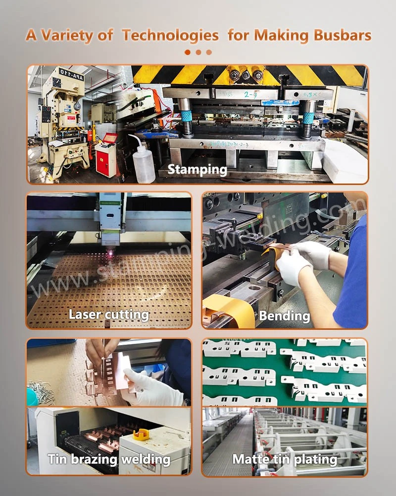
Manufacturing large-format battery busbars requires control over material flatness, terminal position, bend geometry, joining quality, and edge condition. For 3–5 mm copper components, tooling and welding parameters must be selected according to the actual copper grade and component configuration.
Progressive stamping and 3D forming
Precision stamping can produce repeated busbar profiles and mounting features with controlled dimensional relationships.
The manufacturing process may include:
1. Copper sheet or strip incoming inspection.
2. Blanking and piercing.
3. Pilot positioning and progressive forming.
4. Offset and bend formation.
5. Secondary calibration where required.
6. Deburring and edge finishing.
7. Dimensional inspection.
8. Surface treatment or insulation application.
For thick copper components, tooling design should consider punch clearance, material hardness, burr direction, springback, and forming load.
A 3D formed busbar should be inspected against the functional datums used in the module assembly. Measuring individual bends without a consistent datum structure may fail to identify cumulative position errors at the terminal interfaces.
Laser welding for copper busbar assemblies
Laser welding may be used to join copper conductors, terminals, or selected dissimilar-metal components. Copper's high thermal conductivity and high reflectivity at common laser wavelengths make process development important.
Key process variables include:
Laser wavelength and power.
Spot size and beam focus.
Welding speed.
Joint gap and clamping force.
Surface condition and oxide level.
Shielding gas where required.
Weld penetration and interface geometry.
For copper-to-copper joints, the process must produce adequate fusion without excessive spatter, porosity, or distortion. For Cu-Al joints, the formation of brittle intermetallic compounds must be controlled through joint design and process qualification.
Laser welding should be validated through cross-sectional metallography, mechanical testing and electrical resistance measurement.
Joining process comparison for ESS copper busbars
| Joining method | Main mechanism | Advantages | Engineering limitations |
| Laser welding | Concentrated optical energy creates localized fusion | Non-contact joining and precise weld positioning | Copper reflectivity, porosity, and process-window sensitivity |
| Resistance welding | Electrical resistance generates localized heat | Suitable for selected overlapping conductive joints | Electrode wear, current shunting, and joint access |
| Resistance brazing | Resistance heating melts filler material | Can join selected dissimilar geometries | Filler compatibility and thermal exposure |
| Mechanical bolting | Clamping force creates electrical contact | Serviceable and inspectable connection | Torque control, relaxation and contact resistance |
| Molecular diffusion welding | Pressure and temperature create a solid-state bond | Avoids conventional bulk fusion | Requires specialized process control and surface preparation |
The process should be selected according to the required electrical resistance, mechanical load, production rate and inspection access.
Dimensional and joint quality control
| Critical characteristic | Inspection method | Engineering objective |
| Copper thickness | Micrometer or thickness gauge | Verify conductive section |
| Busbar width | Optical measurement or CMM | Confirm cross-section |
| Terminal hole position | CMM or vision measurement | Ensure assembly alignment |
| Formed bend angle | Optical profile measurement | Control module fit |
| Flatness | CMM or surface measurement | Prevent assembly interference |
| Burr height | Optical measurement | Reduce insulation damage risk |
| Weld penetration | Metallographic cross-section | Verify weld geometry |
| Weld discontinuities | Visual and suitable NDT methods | Detect process defects |
| Joint resistance | Four-wire Kelvin measurement | Verify electrical interface |
| Insulation thickness | Coating thickness measurement | Confirm specified dielectric construction |
Prototype development and production validation
For a new 314Ah or 587Ah busbar, prototype development should verify both electrical and mechanical performance before tooling release.
A practical development sequence is:
Drawing and 3D assembly review.
Material and thickness confirmation.
Cross-section and current-density calculation.
Vent clearance and insulation review.
Stamping and forming feasibility assessment.
Laser welding or alternative joining trials.
Dimensional inspection and assembly fit check.
Resistance and temperature-rise testing.
Mechanical displacement and vibration validation.
Customer sample approval and production control planning.
ESS Busbar Design Validation and Quality Documentation
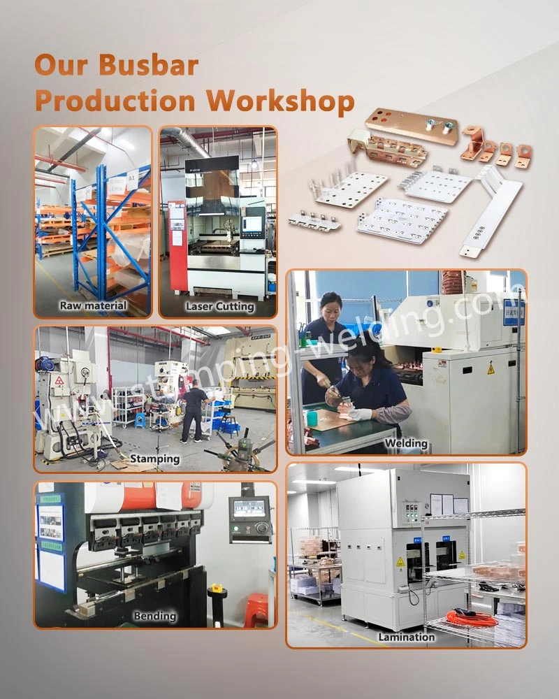
A busbar supplier should provide evidence that the manufactured component meets the drawing and the electrical and mechanical requirements of the battery module.
For large-capacity ESS applications, dimensional inspection alone is insufficient. Validation should cover the conductor, terminal interface, insulation, vent clearance, and mechanical compensation structure.
Recommended validation matrix
| Validation category | Test or inspection | Purpose |
| Material | Material certificate and conductivity verification | Confirm copper grade and electrical properties |
| Dimensional | CMM and optical inspection | Verify 3D geometry and terminal positions |
| Electrical | Four-wire resistance measurement | Confirm conductor and joint resistance |
| Thermal | Continuous-current temperature-rise test | Verify thermal performance |
| Mechanical | Displacement and vibration testing | Evaluate expansion compensation |
| Joining | Weld cross-section and mechanical testing | Verify joint integrity |
| Insulation | Dielectric withstand and insulation resistance tests | Confirm electrical isolation |
| Vent clearance | CAD tolerance analysis and assembly inspection | Preserve pressure-relief path |
| Surface condition | Visual and coating inspection | Identify burrs and insulation defects |
Standards and specification control
The applicable standards depend on whether the busbar is assessed as an individual electrical component, a battery module component, or part of a complete energy storage system.
Relevant references may include:
IEC 62619: Safety requirements for secondary lithium cells and batteries used in industrial applications.
IEC 62933 series: Electrical energy storage systems.
UL 1973: Batteries for stationary and motive auxiliary power applications, where applicable.
UL 9540: Energy storage systems and equipment, where applicable.
UL 94: Flammability classification of plastic materials.
ISO 9001: Quality management system requirements.
IATF 16949: Automotive quality management system requirements where applicable to the supply chain.
These standards do not all apply directly to an individual copper busbar. The buyer should identify the applicable end-product standard, component specification, and required verification scope.
Production traceability and PPAP requirements
For automotive-derived ESS supply chains, customers may request APQP, PFMEA, Control Plan, MSA, SPC and PPAP documentation.
A typical busbar production package may include:
1. Approved drawing and revision history.
2. Copper material certificate.
3. Stamping and forming process flow.
4. Welding procedure and process validation records.
5. Dimensional inspection report.
6. Electrical resistance and temperature-rise results.
7. Insulation test records.
8. Mechanical validation results.
9. PFMEA and Control Plan.
10. PPAP documentation according to the agreed customer submission level.
The required submission level and test frequency should be agreed before mass production. Supplier documentation should identify the production site, material batch, and inspection equipment used.
Engineering Inputs for a 314Ah / 587Ah Busbar OEM Project
The manufacturing feasibility of a large-format ESS busbar depends on the complete module interface rather than the cell capacity alone.
For an accurate DFM review, the engineering package should include:
| Required input | Design purpose |
| Cell model and manufacturer | Confirm terminal and vent configuration |
| Cell capacity and rated current | Establish operating current conditions |
| Continuous and peak current profile | Determine electrical design load |
| Copper grade and temper | Confirm conductivity and formability |
| Required busbar thickness and width | Establish initial cross-section |
| Terminal dimensions and fastening method | Define electrical interface |
| Cell swelling data | Determine expansion compensation geometry |
| Vent keep-out area | Prevent obstruction of pressure-relief discharge |
| Insulation specification | Establish dielectric and thermal requirements |
| Assembly 3D model | Check clearance and tolerance stack-up |
| Annual demand and prototype quantity | Plan tooling and production route |
| Applicable validation standards | Define testing and documentation requirements |
A supplier should not confirm a 300–600A rating based only on a copper cross-section. The final design must account for conductor length, installation environment, terminal resistance, thermal dissipation, and the complete ESS operating profile.
FAQ: 314Ah and 587Ah ESS Copper Busbar Manufacturing
1. What copper busbar thickness is suitable for a 314Ah or 587Ah energy storage cell?
A 3–5 mm copper thickness can be used as an initial design range, but the final cross-section depends on continuous current, conductor width, installation conditions, terminal resistance, and temperature-rise limits.
2. How can an ESS busbar avoid blocking a prismatic cell thermal runaway vent?
Use the cell manufacturer's vent keep-out dimensions and discharge direction to define the busbar routing. Verify worst-case clearance through 3D assembly analysis, tolerance stack-up, and module-level safety assessment.
3. Why are U-shaped or Ω-shaped expansion structures used in large-capacity ESS busbars?
These formed sections provide controlled mechanical compliance to accommodate relative cell movement and thermal expansion. Their bend radius, thickness, and fatigue performance must be validated against the module's displacement and vibration requirements.
contact us