Copper-Clad Aluminum (CCA) and Bimetal Transition Plates: Eliminating Galvanic Corrosion in Heavy Power
Nov 04, 2026
Copper-clad aluminum (CCA) conductors and Cu-Al bimetal transition plates provide a metallurgically bonded interface between copper and aluminum, reducing the reliability risks associated with direct dissimilar-metal connections in substations, energy storage systems, and high-current electrical cabinets. Their performance depends on bond integrity, interface resistance, thermal-cycle stability, and the ability to manufacture holes and bends without initiating interfacial separation. Material selection and joint design must therefore be validated through mechanical, electrical, and thermal testing rather than judged by appearance alone.
Galvanic Corrosion at Copper-Aluminum Interfaces in High-Current Systems
Copper and aluminum are widely used in power distribution because of their electrical conductivity, weight, and cost characteristics. However, direct contact between these metals can create a galvanic corrosion couple when moisture or another conductive electrolyte reaches the interface.
In substations, ESS high-voltage cabinets, and industrial power distribution equipment, this risk is particularly relevant to busbar connections exposed to condensation, temperature fluctuations, airborne contaminants, or outdoor environments.
Why direct Cu-Al contact causes galvanic corrosion
Galvanic corrosion occurs when dissimilar metals with different electrochemical potentials are electrically connected in the presence of an electrolyte. Under these conditions, the more anodic metal tends to corrode preferentially.
In a typical copper-aluminum connection:
Aluminum generally acts as the anodic material relative to copper.
Copper acts as the more cathodic material.
Moisture or condensation can provide the electrolyte path.
The exposed aluminum surface may undergo oxidation and corrosion.
Corrosion products can increase interface resistance and weaken the connection.
The corrosion rate is affected by electrolyte conductivity, temperature, exposure duration, surface condition, and the relative exposed areas of the two metals.
The area ratio is important. A relatively small exposed aluminum anodic region connected to a much larger copper cathodic region can experience concentrated corrosion attack.
Electrical consequences of an unstable Cu-Al connection
An electrical joint with increasing interface resistance generates additional heat under load according to Joule's law:
This heat is concentrated around the connection rather than distributed uniformly across the complete busbar.
Potential consequences include:
Localized temperature rise at bolted interfaces.
Accelerated oxidation and contact degradation.
Loss of clamping force due to thermal expansion and relaxation.
Increased maintenance requirements.
Reduced connection reliability under cyclic loading.
Direct connection versus metallurgically bonded Cu-Al transition
| Connection design | Interface structure | Corrosion exposure | Main engineering concern |
| Direct Cu-Al bolted connection | Separate copper and aluminum surfaces in contact | Exposed dissimilar-metal interface | Moisture ingress and contact degradation |
| Surface-plated aluminum connection | Coating separates the substrate from the contact surface | Depends on coating continuity and damage | Coating wear, porosity, and interface preparation |
| Mechanical transition connector | Separate Cu and Al components joined mechanically | Depends on sealing and joint geometry | Contact pressure and long-term resistance |
| Cu-Al bimetal transition plate | Metallurgically bonded copper and aluminum layers | Bonded interface is not an exposed bolted contact interface | Bond integrity and environmental protection |
| Copper-clad aluminum conductor | Aluminum core with a bonded copper layer | Depends on cladding continuity and edge protection | Cladding thickness and bond continuity |
A bimetal transition plate does not eliminate every corrosion mechanism. Exposed aluminum edges, damaged cladding, moisture ingress, and unsuitable terminal geometry can still create corrosion risks. The design must protect the transition region and control the exposed metal surfaces.
Roll-Bonded and Explosion-Bonded Cu-Al Transition Plates
Copper-aluminum bimetallic materials are produced through different bonding processes. Two common approaches are roll bonding and explosive bonding. Both aim to create a metallurgical connection between copper and aluminum, but their manufacturing mechanisms and suitable product geometries differ.
Roll bonding for copper-clad aluminum materials
Roll bonding applies high pressure through a rolling mill to bring prepared copper and aluminum surfaces into intimate contact. Surface preparation and plastic deformation disrupt surface films and promote solid-state bonding.
The process typically involves:
1. Surface preparation and removal of contamination.
2. Controlled alignment of copper and aluminum layers.
3. Pressure application through rolling.
4. Bond consolidation through plastic deformation.
5. Subsequent heat treatment or finishing where specified.
6. Bond integrity and dimensional inspection.
Important variables include reduction ratio, rolling pressure, material hardness, surface roughness, temperature, and initial layer thickness.
The oxide films on aluminum and copper must be controlled because residual contamination can reduce bonding continuity.
Explosion bonding for heavy-duty transition plates
Explosion bonding uses controlled explosive energy to accelerate one metal plate toward another. The impact creates a high-pressure collision at the interface, producing a metallurgical bond.
Depending on material combination and process conditions, the interface may exhibit a characteristic wavy morphology. This morphology is not, by itself, proof of acceptable bond quality. Excessive localized melting, brittle intermetallic formation, or discontinuous bonding must be evaluated through appropriate metallographic and mechanical tests.
Explosion bonding is commonly considered for larger or thicker transition plates where the product geometry and production economics support the process.
Roll bonding versus explosion bonding
| Engineering factor | Roll bonding | Explosion bonding |
| Bonding mechanism | High-pressure plastic deformation | High-velocity impact bonding |
| Production format | Continuous or batch rolling | Typically plate-based |
| Typical product geometry | Sheets, strips, and selected laminated sections | Heavy plates and transition blanks |
| Thickness flexibility | Depends on rolling equipment and material reduction | Suitable for selected thick-section combinations |
| Interface morphology | Deformed and consolidated solid-state interface | May show characteristic wavy interface |
| Main process variables | Reduction ratio, surface preparation, and rolling conditions | Collision angle, velocity, stand-off,f and explosive loading |
| Typical quality risks | Incomplete bonding, oxide inclusion and thickness variation | Local melting, interface defects and dimensional distortion |
| Downstream processing | Slitting, stamping, bending and machining | Cutting, machining, drilling and forming where feasible |
Neither process should be selected based only on the nominal copper-to-aluminum thickness ratio. The intended current, mechanical loading, transition geometry, operating environment and downstream forming operations must also be considered.
Metallurgical interface and intermetallic compound control
Copper and aluminum can form intermetallic compounds under certain thermal conditions. These phases may exhibit different mechanical properties from the parent metals and can affect interface toughness.
The interface should therefore be evaluated for:
Bond continuity.
Interfacial voids or unbonded areas.
Cracks and local separation.
Excessive reaction layers.
Local melting or brittle phases.
Interface thickness variation where relevant.
Thermal exposure during subsequent processing, including brazing, welding, or heat treatment, may alter the interface condition. Any secondary thermal process must be evaluated against the original bond qualification.
Request Cu-Al Bimetal DFM Evaluation
Mechanical and Electrical Validation of Cu-Al Bimetal Interfaces
A metallurgically bonded transition plate must maintain both mechanical integrity and low electrical resistance. Mechanical testing verifies the bond's resistance to separation, while electrical testing evaluates the quality and stability of the current path.
A visually continuous interface is not sufficient evidence of acceptable performance.
Interfacial shear strength testing
Shear testing evaluates the resistance of the bonded interface to relative movement between the copper and aluminum layers.
A representative test arrangement applies a controlled load parallel to the bond interface. The test specimen geometry and loading method must be defined to minimize bending and stress concentration.
The nominal shear strength can be calculated as:
The calculation method must match the test specimen geometry. For non-uniform stress distributions, the calculated value should be treated as a nominal engineering result rather than the exact local interface stress.
Mechanical test methods for Cu-Al transition plates
| Test method | Evaluation objective | Typical failure indication |
| Interfacial shear test | Resistance to sliding along the bond | Interface separation |
| Peel test | Bond continuity in suitable thin-layer constructions | Progressive layer separation |
| Tensile test | Overall bonded material strength | Parent-metal or interface fracture |
| Bend test | Bond integrity during deformation | Cracking or delamination |
| Metallographic section | Internal interface condition | Voids, cracks, or discontinuities |
| Thermal cycling | Bond stability after repeated temperature changes | Progressive interface separation |
Acceptance criteria should be established using the applicable material specification, product drawing, ng and customer qualification plan. A universal shear-strength threshold should not be applied to every Cu-Al product because thickness, bonding process, ess and specimen geometry differ.
Four-wire interface resistance measurement
The electrical resistance of a Cu-Al transition should be measured using a controlled four-wire method where low-resistance accuracy is required.
The measurement setup should define:
Current injection points.
Voltage sensing locations.
Contact pressure and fixture configuration.
Specimen temperature.
Stabilization time.
Test current.
Instrument accuracy and calibration status.
The measurement should distinguish the resistance of the bonded transition from the resistance of the external bolted interfaces whenever the test geometry permits.
For a complete transition assembly, resistance may include several contributions:
This simplified expression illustrates why the test configuration matters. If the voltage probes include the external terminals, the measured value cannot be attributed solely to the metallurgical bond.
Electrical resistance and current-path validation
| Validation item | Purpose | Recommended control |
| Initial interface resistance | Establish baseline bond performance | Four-wire Kelvin measurement |
| Resistance after thermal cycling | Detect bond degradation | Repeat measurement at controlled temperature |
| Resistance after mechanical forming | Identify damage caused by bending or punching | Test representative finished parts |
| Temperature rise | Evaluate heat generation under current | Defined current and ambient conditions |
| Current cycling | Assess electrical stability under repeated loading | Customer-defined current profile |
| Terminal connection resistance | Separate bolted-joint effects from bond performance | Independent voltage-sensing points |
The resistance limit should be derived from the current rating, permissible temperature rise, geometry, and customer specification. A low initial resistance does not prove long-term stability if the bond is susceptible to thermal fatigue or mechanical separation.
Thermal cycling and delamination resistance
Copper and aluminum have different coefficients of thermal expansion. Repeated temperature changes can therefore generate cyclic stresses within a bonded transition.
The severity depends on:
Copper and aluminum layer thickness.
Bond interface geometry.
Temperature range and dwell time.
Heating and cooling rate.
Residual stress from the bonding process.
Mechanical constraints imposed by the busbar assembly.
A thermal-cycle qualification should specify the temperature limits, number of cycles, dwell time, and transition-plate mounting condition.
After cycling, the specimens should be evaluated for interface separation, dimensional change, and electrical resistance variation.
Temperature Rise and High-Current Performance in ESS and Substation Cabinets
The current-carrying performance of a Cu-Al transition plate depends on the electrical resistance of the complete current path, conductor cross-section, heat dissipation, and terminal configuration.
A transition plate must be evaluated as part of the actual busbar assembly rather than as an isolated material coupon.
Joule heating and conductor cross-section
Conductor heating is governed by current, resistance, and operating duration. The resistance of a uniform conductor can be estimated using:
For a multilayer CCA conductor, current distribution depends on the electrical properties and geometry of each layer, as well as the integrity of the bonded interface. It should not be assumed that all current flows exclusively through the copper cladding or that the aluminum core contributes nothing.
Temperature-rise factors in a Cu-Al transition assembly
| Design factor | Thermal or electrical effect | Engineering response |
| Copper layer thickness | Changes current distribution and conductor resistance | Verify layer ratio against current requirement |
| Aluminum core thickness | Influences total cross-section and mass | Optimize cross-section and structural requirements |
| Bond interface resistance | Generates localized heat | Validate bond quality and resistance |
| Bolted terminal pressure | Affects contact resistance | Define torque and joint assembly controls |
| Surface oxidation | Can increase external contact resistance | Control surface preparation and protection |
| Ventilation and enclosure layout | Affects heat dissipation | Validate in the actual cabinet configuration |
| Adjacent conductor spacing | Influences thermal interaction | Evaluate the complete busbar arrangement |
Cu-Al transition plates in ESS and substation applications
Typical application locations include:
Copper-to-aluminum transitions in high-voltage distribution cabinets.
Transformer and switchgear busbar connections.
ESS battery cluster and power conversion system connections.
Industrial power distribution panels.
Outdoor substation busbar interfaces.
High-current connections between copper terminals and aluminum conductors.
The final transition design should account for rated current, short-circuit withstand requirements, ambient temperature, enclosure ventilation, terminal torque, and environmental exposure.
Environmental protection for Cu-Al interfaces
A metallurgically bonded interface reduces the risk associated with direct copper-aluminum contact, but environmental protection remains necessary.
Recommended design measures include:
Protecting exposed aluminum edges from moisture ingress.
Applying compatible surface treatments where specified.
Avoiding coating damage during punching and bending.
Controlling contact-surface preparation before bolted assembly.
Using appropriate sealing or enclosure protection for outdoor installations.
Preventing water accumulation around transition joints.
Surface treatments must not compromise the electrical contact area. Any coating or sealant applied near a bolted interface should be compatible with the connection design and specified contact resistance.
Request Busbar Electrical Design Review
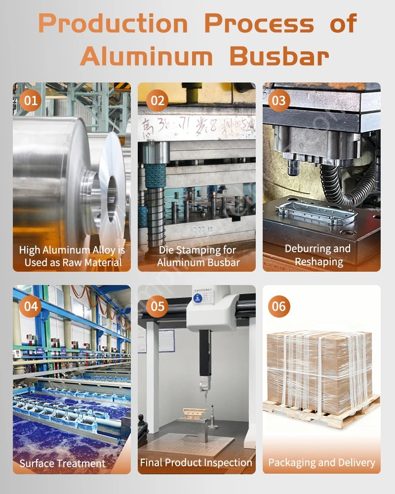
CNC Bending, Punching and DFM Requirements for Cu-Al Composite Busbars
The metallurgical bond must remain intact during downstream manufacturing. Punching, shearing and CNC bending introduce local stresses that can cause edge cracking, layer separation or interface damage if the tooling and geometry are unsuitable.
DFM review should therefore be performed before production tooling is released.
CNC bending and interface stress control
During bending, the outer layer experiences tensile strain while the inner layer experiences compressive strain. Because copper and aluminum have different mechanical properties and thermal expansion behavior, their deformation response may not be identical.
The following factors should be evaluated:
Bend radius relative to total thickness.
Copper-to-aluminum thickness ratio.
Bend direction relative to the bonded interface.
Material temper and work-hardening condition.
Tooling radius and punch clearance.
Distance between the bend line and the interface termination.
A minimum bend radius should not be assigned solely from the overall thickness. It should be validated using the actual composite construction and bonding process.
Bending considerations for Cu-Al composite material
| DFM factor | Potential failure | Recommended engineering control |
| Small internal bend radius | Outer-layer cracking or interface separation | Validate minimum radius through bend trials |
| Unequal layer thickness | Non-uniform strain distribution | Review layer ratio and neutral-axis position |
| Bend line near interface termination | Edge delamination | Define minimum edge distance |
| Incorrect bend orientation | Increased tensile stress at vulnerable interface regions | Confirm bend direction through DFM |
| Excessive springback | Dimensional deviation | Establish material-specific compensation |
| Repeated reverse bending | Work hardening and fatigue damage | Avoid unnecessary re-bending |
The neutral axis of a multilayer composite does not necessarily lie at the geometric center. Layer modulus, thickness, and plastic deformation behavior influence the strain distribution.
Punching and shearing near the bonded interface
Punching a Cu-Al composite busbar creates a sheared edge through both metal layers. Incorrect clearance or unsuitable tooling can cause burr formation, layer displacement, or local delamination.
The following controls should be considered:
1. Select punch-die clearance based on the composite thickness and material properties.
2. Maintain sharp cutting edges to reduce excessive deformation.
3. Avoid locating holes too close to the interface termination.
4. Inspect punched edges for cracks and layer separation.
5. Confirm that burr orientation does not interfere with insulation or assembly.
6. Validate the finished component after subsequent bending.
For critical applications, sectioning of representative punched and bent samples can confirm whether the interface remains continuous after forming.
Recommended manufacturing sequence for composite busbars
| Manufacturing stage | Process | Key quality characteristic |
| 1 | Incoming Cu-Al composite inspection | Layer thickness and bond condition |
| 2 | CNC cutting or blanking | Overall dimensions and edge quality |
| 3 | Hole punching or drilling | Hole position, diameter, and burr height |
| 4 | CNC bending | Bend angle, radius, and interface integrity |
| 5 | Deburring and edge finishing | No harmful burrs or delamination |
| 6 | Surface treatment | Coating continuity and contact-area protection |
| 7 | Dimensional inspection | Drawing-based geometry |
| 8 | Electrical and mechanical validation | Resistance and bond integrity |
Cu-Al Transition Plate Design and Quality Control for OEM Production
For OEM production, material qualification, manufacturing control, and finished-part inspection should be linked through a documented process flow.
A transition plate that passes incoming material inspection may still fail after punching, bending, or terminal assembly. The finished geometry must therefore be validated after all manufacturing operations.
Critical-to-quality characteristics
| CTQ characteristic | Inspection method | Quality objective |
| Copper layer thickness | Micrometer or metallographic section | Confirm specified cladding thickness |
| Aluminum layer thickness | Micrometer or metallographic section | Confirm core dimension |
| Total thickness | Thickness gauge | Control overall stack-up |
| Bond continuity | Ultrasonic inspection or metallographic section, where qualified | Identify unbonded areas |
| Interface shear strength | Mechanical shear test | Verify bond strength |
| Interface resistance | Four-wire Kelvin measurement | Verify electrical continuity |
| Bend angle and radius | Optical measurement or CMM | Confirm formed geometry |
| Hole position | CMM or optical measurement | Maintain assembly alignment |
| Burr height | Optical or dimensional inspection | Prevent assembly interference |
| Temperature rise | Current-carrying test | Verify thermal performance |
Inspection frequency should be defined by the control plan and adjusted according to process risk, production volume,olume and customer requirements.
Traceability and process validation
A supplier qualification package for Cu-Al transition plates may include:
Copper and aluminum material certificates.
Composite material layer-thickness records.
Bonding-process qualification records.
Interfacial shear test results.
Metallographic cross-section reports.
Electrical resistance measurements.
Thermal-cycle validation results.
CNC bending and punching inspection records.
Final dimensional reports.
Batch identification and change-control records.
Where the customer requires IATF 16949-related documentation or PPAP submission, the process flow, PFMEA, and Control Plan should include the composite bonding and downstream forming operations.
CCA busbar versus bimetal transition plate: design selection
CCA busbars and bimetal transition plates are related but serve different design functions. CCA generally describes a copper-clad aluminum conductor, while a bimetal transition plate may use a localized Cu-Al bonded region to connect separate copper and aluminum conductors.
| Design factor | Copper-clad aluminum busbar | Cu-Al bimetal transition plate |
| Basic construction | Copper layer bonded to aluminum core | Copper and aluminum sections bonded at a transition |
| Main function | Conductive busbar with composite cross-section | Transition between copper and aluminum conductors |
| Material distribution | Copper cladding along the conductor | Layer arrangement depends on transition geometry |
| Typical application | Weight-sensitive power conductors | Cu-Al terminal and busbar connections |
| Main design concern | Cladding continuity and current distribution | Bond strength and interface resistance |
| Downstream processing | Cutting, punching, bending, and finishing | Cutting, machining, punching,nching and selected forming |
| Main validation | Electrical, mechanical and thermal performance | Interface shear resistance and thermal-cycle stability |
The choice depends on whether the application requires a composite conductor along its length or a localized transition between two different conductor materials.
Apollo Cu-Al Composite Busbar Manufacturing and DFM Support
Apollo Electronic Components (Xiamen) Co., Ltd. supports the development of precision metal components and electrical connection assemblies for EV, ESS, PV, and power distribution applications.
For Cu-Al composite busbars and transition components, manufacturing feasibility should be reviewed against the complete drawing and operating conditions rather than the nominal material combination alone.
Engineering review can cover:
Copper and aluminum layer configuration.
Transition plate geometry and interface location.
Punching, drilling, and CNC bending feasibility.
Hole-to-edge distance and fastener layout.
Surface treatment and exposed-edge protection.
Electrical resistance and current-carrying requirements.
Mechanical retention and interface validation.
Finished-part dimensional inspection.
For projects involving dissimilar-metal connections, the transition design should be assessed together with the mating copper and aluminum terminals, bolted-joint arrangement, and environmental protection method.
FAQ: Copper-Clad Aluminum Busbar and Bimetal Transition Plate
1. How does a Cu-Al bimetal transition plate reduce galvanic corrosion?
It provides a metallurgically bonded transition between copper and aluminum, avoiding a directly exposed Cu-Al contact interface at the transition. Exposed edges and external connections still require appropriate environmental protection.
2. How is the bond strength of a copper-aluminum transition plate tested?
Interfacial shear testing evaluates resistance to sliding, while metallographic sectioning identifies discontinuities and interface defects. Thermal cycling and electrical resistance measurements assess stability after environmental loading.
3. Can a Cu-Al composite busbar be punched and CNC bent after bonding?
Yes, if the composite construction and bond process are suitable for the required deformation. Bend radius, punch clearance, hole edge distance, and forming direction should be validated to prevent cracking or delamination.
contact us