600 amp ct cabinet industry knowledge analysis
May 26, 2026
Physical basis
The operation of a current transformer is based on the laws of electromagnetic induction, but its application is fundamentally different from that of a generator or power transformer. In general knowledge, a closed conductor generates an induced electromotive force in a changing magnetic field, which is the basic expression of the principle of electromagnetic induction. However, there are specific engineering constraints on how current transformers operate. Its primary winding is connected in series in the high-current main circuit under test. The current is determined by the system load and is a forced, unadjustable variable, rather than an independent excitation source specifically applied to generate a magnetic field. The core task of the transformer is to use the alternating magnetic field generated by the current to passively induce a current signal reduced in a fixed proportion in the secondary winding under the premise that the primary side current is forced to pass through. The key feature of this process is the coupling relationship between "forced excitation" and "passive conversion".
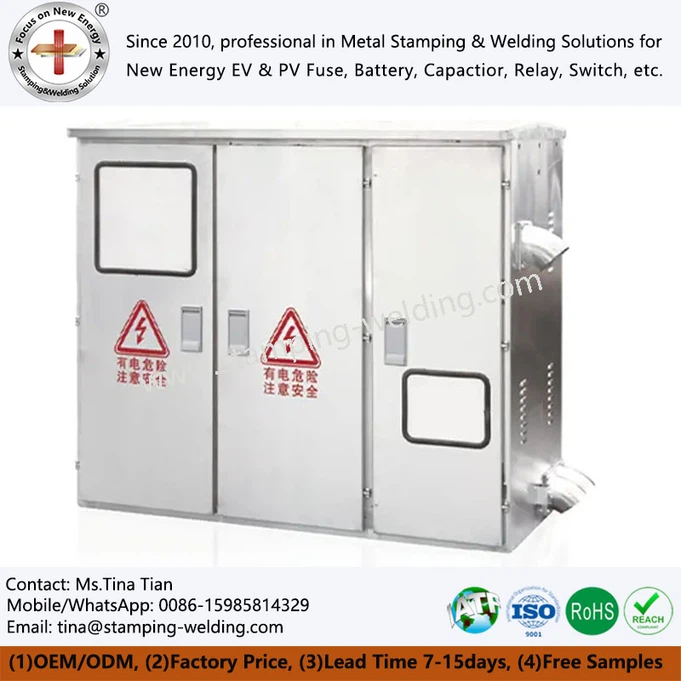
Unlike power transformers that pursue energy transmission efficiency, the design goals of current transformers focus on the linearity of signal transmission and measurement fidelity. In the engineering application of such equipment, it is often necessary to connect the secondary signal output by it to the electrical meter cabinet or electrical supply cabinet to achieve centralized monitoring and measurement of the primary current. At the same time, in order to facilitate on-site debugging and maintenance, it has become a standard practice to reserve the secondary side test terminals of the transformer near the cabinet power outlet.
core structures
The physical structure of the CT-600/5 current transformer can be disassembled into three mutually restrictive components based on functional orientation, and the design of each part serves a specific engineering goal. First, the primary winding and current-carrying conductor. In the feedthrough structure, the primary winding is usually a single-turn copper rod or copper bar, which is directly connected in series to the primary main circuit. The design of this part focuses on mechanical strength, thermal stability and dynamic stability to ensure that the equipment will not be deformed or damaged under the huge electrodynamic impact generated by short-circuit current. The resistance of the primary conductor is deliberately controlled to an extremely low level to minimize the impact on the main circuit power transmission.
Second, the iron core and magnetic circuit system. The iron core is wound with high magnetic permeability cold-rolled silicon steel sheets or nanocrystalline alloy strips to form a closed magnetic circuit. The core contradiction in core design lies in balancing the saturation point and measurement accuracy. The iron core needs to maintain a high degree of linear magnetization characteristics within the normal variation range of the primary side current to avoid premature entry into the saturation zone, resulting in current ratio distortion. The material grade selection and lamination process of the iron core directly affect the size of eddy current loss and hysteresis loss - these two types of losses are the main physical sources of measurement phase error. For miniature current transformers installed near data cabinet power supplies or comms cabinet power bars, their cores are often made of ultra-microcrystalline materials to reduce volume and improve low-frequency response.
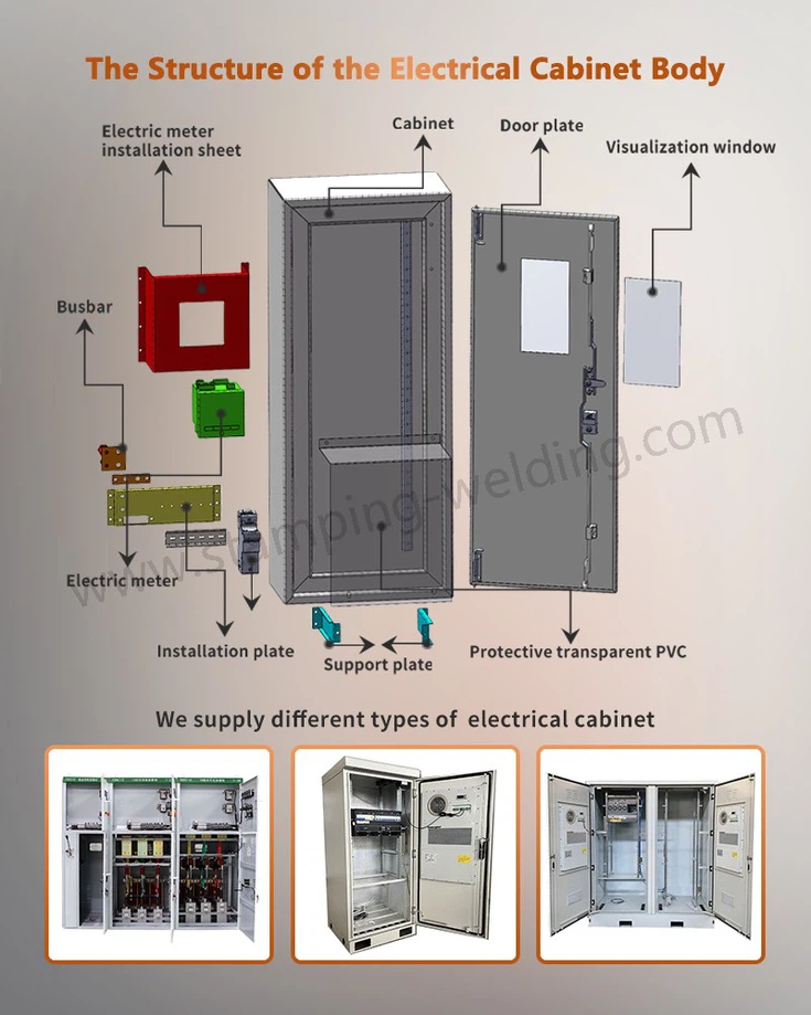
Third, the secondary winding and insulation system. The secondary winding is tightly wound on the iron core, with far more turns than the primary side to achieve the required transformation ratio. The insulation system is a key link to ensure the safety of people and equipment. It must be able to withstand the high voltage from the primary side to the ground and completely isolate this high voltage from the low-voltage circuit on the secondary side. The selection of insulation materials, the control of the winding process and the design of the insulation structure between windings jointly determine the rated insulation voltage level and long-term operating reliability of the equipment. Inside the power supply cabinet, the secondary lead wire of the current transformer is usually connected through a dedicated terminal block, which has a short-circuit function to facilitate the disassembly and assembly of the instrument without a power outage.
Process technology
In the field of industrial manufacturing, the depth and breadth of application of rectifier cabinets continue to expand. Electroplating and electrolysis processes have extremely strict requirements on the steady-current characteristics of DC power supplies. Small fluctuations in current density will directly affect the uniformity of coating thickness or the purity of electrolytic products. Using a silicon-controlled rectifier cabinet with constant current closed-loop control can maintain the stability of the output current within plus or minus five thousandths. The DC motor drive system relies on the rectifier cabinet to provide adjustable DC armature voltage, and realizes motor soft start, speed regulation and regenerative braking by changing the firing angle. Welding equipment requires the rectifier cabinet to output thousands of amps of large pulse current in a short period of time, which places extremely high requirements on the surge tolerance of the device and the thermal stability of the cabinet busbar. In the construction of communication infrastructure, base station rooms and aggregation nodes use a large number of rectifier cabinets to build a negative 48-volt DC basic power supply system, and its output is distributed to each communication equipment cabinet through copper bars.
Some high-density communication sites use comms cabinet power bar as a DC power distribution expansion unit. The total DC bus output from the rectifier cabinet is subdivided into multiple branches to supply power to transmission equipment, wireless equipment and monitoring equipment, respectively, achieving visualization and maintainability of power distribution. In large industrial power distribution rooms, the AC input side of the rectifier cabinet often needs to go through a 1000-amp CT cabinet for current measurement and mutual inductance, providing accurate data support for power management and load analysis.
future trends
Facing the future, rectifier cabinet technology is continuing to evolve along the three main lines of high efficiency, intelligence and modularization. Wide-bandgap semiconductor materials represented by silicon carbide and gallium nitride enable the switching frequency of rectifier devices to break through the upper limit of tens of kilohertz of traditional silicon-based IGBTs and enter the range of hundreds of kilohertz or even megahertz. This means that the volume of filter inductors and capacitors can be greatly reduced, and the power density of rectifier cabinets is significantly improved. In terms of intelligence, the collaboration of embedded sensors, edge computing gateways and cloud operation and maintenance platforms enables the rectifier cabinet to have remote status monitoring, predictive fault maintenance and adaptive parameter optimization capabilities. Operation and maintenance personnel can grasp the health status of the equipment without arriving at the site. The modular design standardizes the rectifier power unit, control unit and power distribution unit into hot-swappable independent modules. When a module fails, it can be replaced without shutting down, and the system availability reaches carrier-grade standards. In integrated power supply and distribution solutions, rectifier cabinets are often integrated with the cabinet with power supply architecture to integrate rectification, energy storage, power distribution and monitoring functions into a single cabinet, providing plug-and-play DC energy interfaces for edge computing nodes and distributed energy stations.
contact us
Whether your project is a new substation, an industrial plant expansion, or a power system upgrade for communication base stations and data centers, choosing a current transformer that is accurate, reliable, safe and compliant is a prerequisite for ensuring the accurate operation of the entire power monitoring system - contact our engineering and technical team immediately to obtain a 600 amp ct cabinet customized selection plan and technical support for your specific voltage level and accuracy requirements.