Complete Guide to EV Capacitor Busbar: Integrating Film Capacitors with Custom Busbar Assemblies
Aug 18, 2026
For 800V electric drive systems, the EV Capacitor Busbar Custom design must control current-loop inductance, connection resistance, creepage distance and mechanical stress between the DC-Link film capacitor and inverter power stage. A properly engineered DC-Link Busbar Assembly combines conductor geometry, insulation and joining processes into one controlled electrical path.

DC-Link Busbar Assembly: Electrical Design for 800V SiC Inverters
The DC-Link busbar connects the film capacitor to the inverter switching stage and carries high-frequency pulsed current generated by SiC power modules. Unlike a simple flat copper bar, the assembly must be designed around the complete current loop.
Key engineering variables include:
- C1100 copper: electrical conductivity typically above 100% IACS in suitable annealed grades.
- Low loop inductance: laminated positive/negative conductors can reduce magnetic loop area.
- Controlled resistance: contact surfaces and welded joints must maintain stable electrical resistance.
- Creepage and clearance: spacing must match the DC voltage, insulation system and applicable vehicle requirements.
- Current density: conductor width and thickness are selected according to RMS current, pulse current and allowable temperature rise.
For high-frequency SiC switching, reducing the physical distance between forward and return current paths is particularly important. A compact laminated arrangement can reduce parasitic inductance and associated voltage overshoot during rapid switching events.
| Design Factor | Typical Engineering Focus |
|---|---|
| Conductor | C1100 / high-conductivity copper |
| Voltage platform | 400V / 800V EV systems |
| Current | Continuous and pulse current profile |
| Inductance | Minimize current-loop area |
| Insulation | Film, molded, powder-coated or sleeve systems |
| Dimensional control | Based on inverter and capacitor interfaces |
Low-Profile Busbar Geometry and Vibration Control
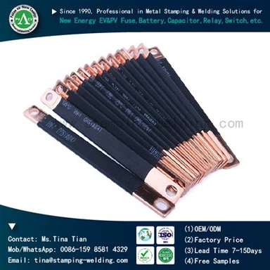
The physical interface between the film capacitor and inverter often has limited vertical space. A low-profile busbar can reduce package height while maintaining the required conductor cross-section.
The design normally combines precision cutting, bending, stamping, drilling or CNC machining. Edge chamfering is used where sharp copper edges could damage insulation or create local electric-field concentration.
Mechanical reliability also depends on how the busbar is fixed to the capacitor and inverter housing. Excessive rigidity can transfer vibration and thermal expansion directly into terminals. Controlled bending zones, mounting points and compliant interfaces help accommodate dimensional variation during vehicle operation.
For EV applications, the design should therefore consider:
- ±0.05 mm to ±0.10 mm interface tolerances where required by the assembly.
- Thermal expansion between copper, aluminum housings and polymer components.
- Vibration loading around bolted or welded joints.
- Resonance risk caused by unsupported conductor sections.
- Clearance from the inverter housing and adjacent conductive components.
Need a compact DC-Link busbar for an 800V inverter package?
Request EV Capacitor Busbar DFM Review
Laser Welding and Ultrasonic Joining for Copper Busbar Assemblies
The connection method has a direct effect on resistance, mechanical strength and production consistency. For copper conductors, laser welding and ultrasonic metal welding are both viable, but their process windows differ.
| Joining Method | Main Advantage | Main Engineering Consideration |
|---|---|---|
| Laser welding | Precise, localized heat input | Joint gap, reflectivity and penetration control |
| Ultrasonic welding | Low bulk heating | Tool pressure, amplitude and weld area |
| Resistance welding | Fast cycle time | Current distribution and electrode wear |
| Bolted connection | Easy serviceability | Contact resistance and torque control |
Laser welding is suitable where the joint geometry requires controlled penetration or access from a defined direction. Ultrasonic welding is useful for thin copper components where minimizing bulk thermal exposure is important.
For production qualification, joint resistance, pull force, cross-section and weld appearance should be evaluated together rather than relying only on visual inspection. Metallographic cross-sections can reveal incomplete fusion, voids, excessive penetration and interfacial defects that are not visible externally.
Insulation and Encapsulation for High-Voltage DC-Link Systems
An EV capacitor busbar must electrically isolate adjacent conductors while maintaining dimensional stability under temperature cycling and vibration. Depending on the package architecture, insulation may use laminated dielectric films, heat-shrink sleeves, molded insulation or epoxy-based systems.
The selection should consider:
- Dielectric strength of the insulation material.
- Required creepage and clearance distances.
- Operating temperature and thermal cycling.
- Resistance to abrasion during assembly.
- Adhesion and dimensional stability.
- Compatibility with coolant, oil and other automotive fluids.
For some assemblies, insulation and encapsulation are combined after welding to protect exposed conductive areas. The encapsulation process must avoid voids around high-voltage interfaces because trapped air can reduce dielectric margin and create localized electrical stress.
For an 800V platform, insulation design should be validated according to the actual system voltage, pollution level, material group, environmental conditions and applicable automotive standards rather than selecting an insulation thickness based on voltage alone.

800V SiC Drive Applications: From Prototype to Mass Production
The shift toward 800V architectures and SiC switching devices increases the electrical and mechanical demands placed on the DC-Link connection.
A typical architecture places the film capacitor close to the inverter DC terminals to shorten the high-current loop. The busbar geometry then follows the capacitor terminal position, inverter terminal arrangement and available housing space.
A production-ready Film Capacitor Copper Busbar Supplier should therefore be able to support more than copper fabrication. Engineering work may include:
- 2D/3D drawing review for interface and clearance conflicts.
- DFM analysis for bending, machining and joining operations.
- Prototype production for electrical and mechanical validation.
- Welding parameter development and joint inspection.
- Insulation validation according to the final system requirements.
- Dimensional inspection using CMM or dedicated gauges.
- Process control for transition from prototype to repeat production.
For Tier 1 and Tier 2 EV suppliers, the production package may also require material certificates, process flow charts, control plans, inspection records and PPAP documentation.
Key Selection Criteria for an EV Capacitor Busbar Supplier
When sourcing an EV Capacitor Busbar Custom solution, procurement and engineering teams should evaluate the manufacturing process together with the electrical design.
A suitable supplier should demonstrate:
- C1100 copper processing and material traceability.
- Precision cutting, bending and CNC machining.
- Copper-to-copper and dissimilar-metal welding capability where required.
- Insulation and encapsulation process control.
- CMM dimensional inspection for critical interfaces.
- Electrical resistance and dielectric testing.
- Prototype and mass-production capacity.
- ISO 9001 or IATF 16949 quality-system capability where required.
- PPAP documentation support for automotive programs.
The supplier's ability to control the entire manufacturing chain is particularly important when the busbar contains several integrated operations. Separating copper processing, welding and insulation among multiple suppliers can increase interface risks during development and production ramp-up.

FAQ
Q: What copper grade is commonly used for EV capacitor busbars?
A: C1100 pure copper is commonly selected where high electrical conductivity is required. Final material selection depends on conductivity, mechanical requirements, forming conditions, surface treatment and the customer's electrical design specification.
Q: How can a DC-Link busbar reduce parasitic inductance?
A: The primary approach is to reduce the physical loop area by placing positive and negative conductors close together. Laminated or closely spaced conductor structures can reduce magnetic flux linkage and voltage overshoot during fast SiC switching.
Q: Which joining process is suitable for copper capacitor busbars?
A: Laser welding, ultrasonic welding, resistance welding and mechanical fastening can all be used. The choice depends on copper thickness, joint geometry, electrical resistance targets, available access and required mechanical strength.
Q: Can an EV capacitor bar be customized for 800V systems?
A: Yes. The conductor thickness, width, bending geometry, terminal position, insulation structure and mounting features can be designed around the capacitor and inverter interfaces. Electrical clearance and thermal requirements must be verified during engineering review.
Q: What documents are normally required for automotive busbar production?
A: Automotive projects may require material certificates, dimensional inspection records, process flow, PFMEA, control plans, capability studies and PPAP documentation. The exact submission level depends on the customer's quality requirements.
Contact Us
For 800V EV drive systems, share your busbar layout, capacitor interface, and electrical requirements to evaluate the right DC-Link connection design.