Insulation Coating Solutions for High-Voltage Copper Busbars and Stamped Components
Nov 11, 2026
High-voltage copper busbars installed in compact distribution cabinets require controlled electrical insulation, adequate dielectric strength, and resistance to thermal and mechanical degradation. Epoxy powder coating, PVC hot-dip coating, and heat-shrink tubing provide different levels of dielectric protection, coverage, and dimensional control. Selecting the correct insulated copper busbar coating requires evaluating operating voltage, clearance, creepage distance, temperature rise, coating thickness, and applicable flame-retardancy requirements such as UL 94 V-0.
Xiamen Apollo Stamping Welding Technology Co., Ltd. manufactures copper busbars and precision stamped electrical components with integrated metal stamping, surface preparation, and insulation coating processes for EV power distribution, energy storage systems, photovoltaic equipment, and industrial electrical cabinets.
Electrical Insulation Requirements for High-Voltage Copper Busbars in Compact Distribution Cabinets
Preventing Arc Flashover in High-Density Electrical Assemblies
As power density increases, copper busbars are installed closer together inside distribution cabinets, inverter systems, and high-voltage battery assemblies. Reduced installation space increases the importance of insulation integrity and electrical spacing.
An insulation failure can result in:
Phase-to-phase short circuits.
Phase-to-ground electrical faults.
Surface tracking caused by contamination and moisture.
Partial discharge under applicable high-voltage conditions.
Arc propagation between adjacent conductive components.
The insulation design must account for the complete electrical assembly rather than relying exclusively on the coating's dielectric strength.
Four parameters determine the insulation system's performance:
| Parameter | Engineering Significance | Verification Method |
| Operating voltage | Determines electrical stress | Rated-voltage verification |
| Dielectric strength | Indicates material resistance to electrical breakdown | IEC 60243-1 testing |
| Clearance | Shortest distance through air between conductive parts | Dimensional inspection |
| Creepage distance | Shortest path along an insulating surface | Drawing and assembly inspection |
| Coating thickness | Influences dielectric protection and dimensional fit | Thickness gauge |
| Flame retardancy | Evaluates material behavior under specified fire exposure | UL 94 testing |
Important design distinction: Dielectric breakdown strength, clearance, and creepage distance are separate engineering characteristics. A coating with a high dielectric strength does not automatically compensate for insufficient air clearance or creepage distance.
Copper Busbar Materials and Surface Preparation
Copper busbars commonly use C11000 (ETP copper), C10200 (oxygen-free copper), or equivalent grades according to electrical and manufacturing requirements.
| Material | Electrical Characteristics | Typical Application |
| C11000 copper | Approximately 100% IACS conductivity for standard annealed reference material | Power distribution busbars |
| C10200 copper | High conductivity with controlled oxygen content | High-current electrical connections |
| C26800 brass | Lower conductivity than pure copper | Mechanical terminals and stamped hardware |
| Aluminum 1060 | Approximately 61% IACS conductivity | Lightweight power distribution components |
Before applying insulation, copper surfaces require appropriate cleaning and pretreatment.
Typical contamination includes:
Drawing and stamping lubricants.
Oxide films.
Metal particles.
Handling residues.
Moisture and surface contaminants.
Surface preparation directly affects coating adhesion and long-term insulation reliability.
Comparison of Three Insulated Copper Busbar Coating Processes
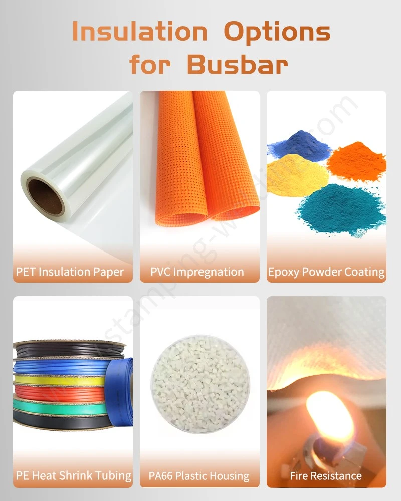
The three main insulation methods used for copper busbars are epoxy resin powder coating, PVC hot-dip coating, and heat-shrink tubing.
Their performance differs in coating uniformity, edge coverage, mechanical protection, and suitability for complex geometries.
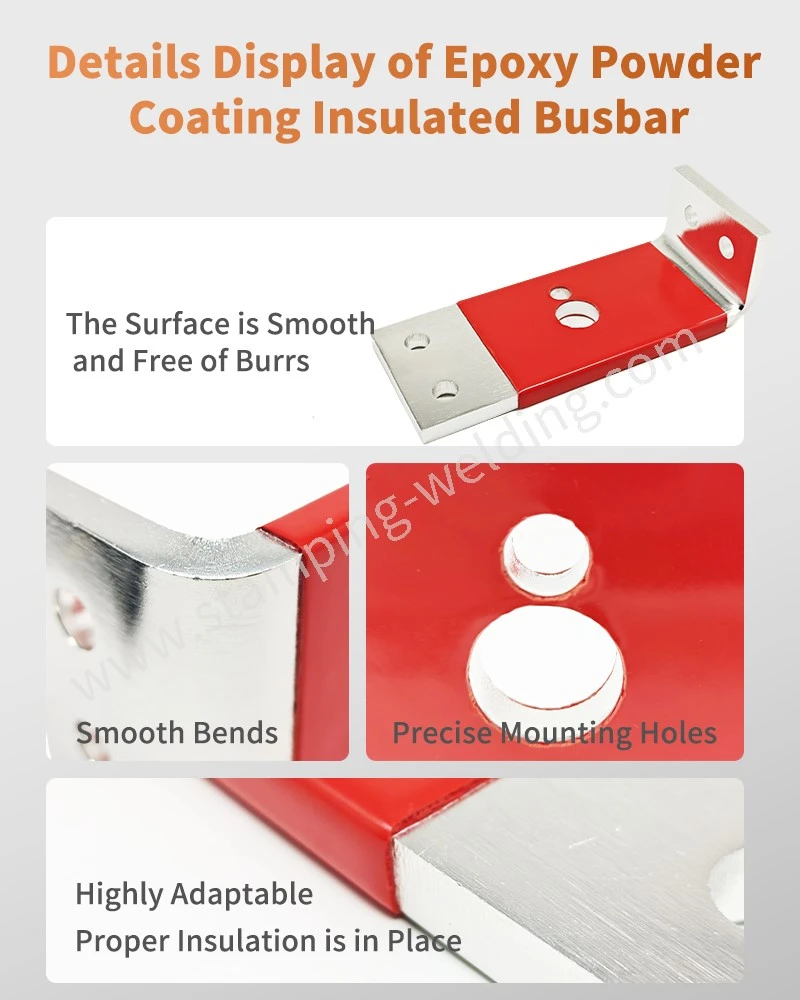
Epoxy Resin Powder Coating for High-Voltage Copper Busbars
Epoxy powder coating is commonly used for rigid copper busbars in electrical distribution cabinets.
The process typically includes:
1. Copper busbar stamping, bending, or machining.
2. Degreasing and surface cleaning.
3. Chemical pretreatment where required.
4. Electrostatic application or fluidized-bed powder coating.
5. Thermal curing according to the powder manufacturer's specification.
6. Coating thickness and adhesion inspection.
For fluidized-bed coating, preheated metal components are immersed in suspended thermosetting powder. The powder melts and forms an insulating layer on the component surface.
Key engineering variables include:
Substrate preheating temperature.
Powder particle characteristics.
Immersion time.
Coating thickness.
Curing temperature and duration.
Copper oxidation during thermal processing.
Epoxy powder coating offers good adhesion and electrical insulation when the substrate preparation and curing cycle are properly controlled.
PVC Hot-Dip Coating for Electrical Metal Components
PVC hot-dip coating forms a polymer insulation layer through immersion in a controlled PVC coating system.
Its main characteristics include:
Flexible insulation layers.
Good moisture resistance.
Mechanical protection against surface abrasion.
Coverage of irregular metal geometries.
Suitability for selected terminals and electrical hardware.
However, PVC formulations have different temperature ratings, dielectric properties, and flame-retardancy characteristics.
Material selection must therefore be based on the specific compound's technical data sheet and qualification results rather than assuming all PVC coatings meet UL 94 V-0.
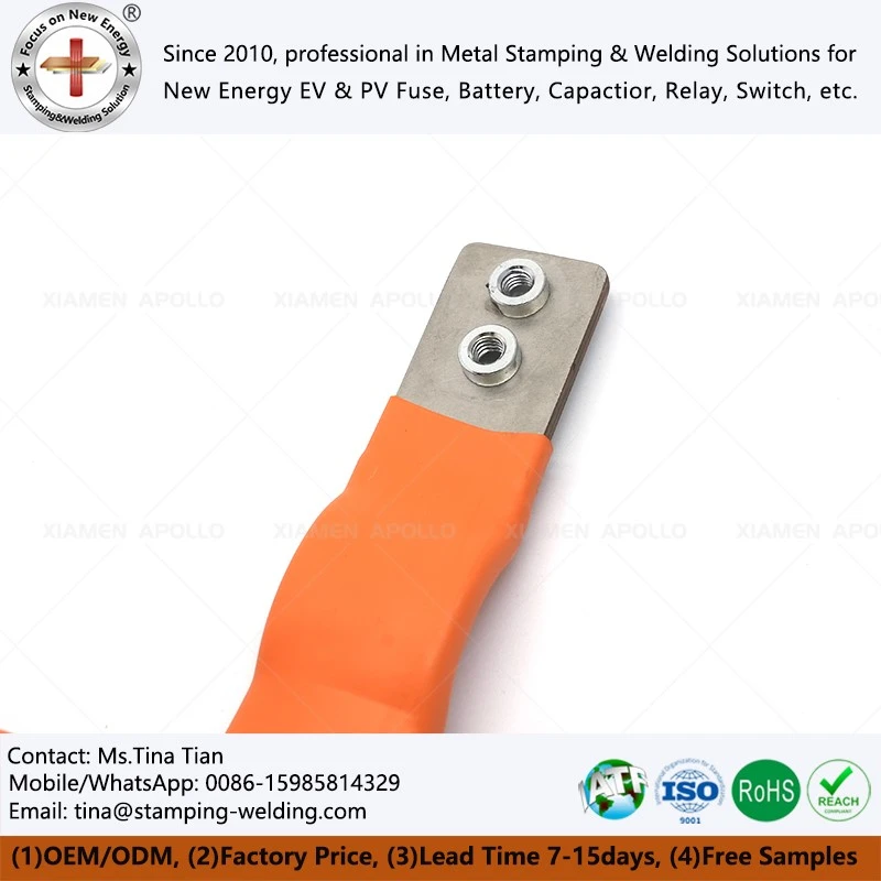
Heat-Shrink Tubing for Copper Busbar Insulation
Heat-shrink tubing is manufactured from polymer tubing that contracts when exposed to a specified heating process.
It is particularly suitable for:
Straight copper busbars.
Flexible copper connectors.
Localized insulation zones.
Retrofit insulation and maintenance applications.
The primary engineering limitation is coverage around complex geometries.
Sharp corners, branching structures, and irregular bends can cause uneven shrinkage or localized stress.
The installation process must control:
Initial tubing diameter.
Shrink ratio.
Recovery temperature.
Overlap length.
End sealing.
Final insulation thickness.
Technical Comparison: Epoxy Powder vs PVC Hot-Dip vs Heat-Shrink
| Evaluation Parameter | Epoxy Powder Coating | PVC Hot-Dip Coating | Heat-Shrink Tubing |
| Insulation structure | Cured thermoset coating | Polymer coating layer | Shrinkable polymer sleeve |
| Coating uniformity | High with controlled application | Depends on immersion conditions | Depends on shrinkage and installation |
| Complex geometry | Requires careful edge coverage validation | Suitable for selected complex profiles | Limited by tubing geometry |
| Adhesion | Depends on pretreatment and curing | Depends on substrate and formulation | Primarily mechanical retention |
| Mechanical protection | Good surface protection | Flexible mechanical protection | Good abrasion protection |
| Thickness control | Process-dependent | Process-dependent | Controlled by tubing specification |
| Repairability | Local repair may require special procedures | Depends on coating system | Sleeve replacement is possible |
| Typical application | Rigid distribution busbars | Electrical terminals and metal parts | Straight and flexible busbars |
The final selection should be based on operating temperature, voltage rating, installation geometry, assembly tolerances, and the required electrical safety standard.
Request Free DFM Evaluation & Quote
Dielectric Strength, UL 94 V-0 and High-Voltage Insulation Validation
Dielectric Breakdown Strength and Coating Thickness
Dielectric strength describes the electric field intensity at which an insulating material undergoes electrical breakdown under specified test conditions.
For example, a coating with a dielectric strength of 15 kV/mm and a thickness of 0.5 mm would have a theoretical breakdown voltage of
kV under an idealized uniform-field assumption.
This is not a guaranteed product withstand voltage. Actual breakdown performance depends on coating defects, electrode geometry, substrate edges, test conditions, and environmental exposure.
For insulated copper busbar production, coating thickness must be specified alongside the required dielectric test voltage.
| Engineering Parameter | Specification Consideration | Inspection Method |
| Dielectric strength | Material-specific kV/mm rating | IEC 60243-1 |
| Coating thickness | Customer-defined minimum and maximum | Coating thickness gauge |
| Withstand voltage | Assembly-level test requirement | Dielectric withstand tester |
| Insulation resistance | Minimum resistance under specified conditions | Insulation resistance tester |
| Adhesion | Resistance to coating separation | Applicable adhesion test |
| Surface defects | No exposed conductive substrate in critical zones | Visual and electrical inspection |
UL 94 V-0 Flame Retardancy Requirements
UL 94 evaluates the flammability characteristics of plastic materials under defined laboratory conditions.
UL 94 V-0 classification includes specific vertical burning requirements:
Afterflame time for each specimen does not exceed 10 seconds.
Total afterflame time for the specified sequence does not exceed 50 seconds.
No specimen burns up to the holding clamp.
Flaming particles must not ignite the cotton indicator.
For copper busbar insulation, the selected coating or tubing compound must have supporting test documentation for the applicable material grade and thickness.
A UL 94 V-0 classification does not establish the complete electrical safety of a busbar assembly.
Temperature Resistance and Long-Term Insulation Stability
Copper busbars experience Joule heating during high-current operation.
Higher current and increased contact resistance can raise local temperatures and accelerate insulation aging.
The insulation material must therefore be selected according to:
Continuous operating temperature.
Short-term temperature excursions.
Thermal cycling conditions.
Ambient humidity.
Chemical exposure.
Required service life.
The actual temperature rating must be verified against the coating manufacturer's qualified material data.
Applicable Standards for Electrical Insulation Systems
| Standard | Scope | Relevance |
| IEC 60243-1 | Electrical strength of insulating materials | Dielectric breakdown testing |
| UL 94 | Flammability of plastic materials | V-0 classification |
| IEC 60664-1 | Insulation coordination for low-voltage systems | Clearance and creepage design |
| IEC 61439 | Low-voltage switchgear and controlgear assemblies | Assembly-level verification |
| IEC 60947 | Low-voltage switchgear and controlgear | Applicable electrical equipment requirements |
| ASTM D3359 | Adhesion by tape testing | Coating adhesion evaluation, where applicable |
Standard selection depends on the intended equipment category, voltage rating, and target market.
Coating Defects, Edge Coverage and Quality Control for Insulated Copper Busbars
Preventing Pinholes and Exposed Copper at Sharp Edges
One of the most common risks in metal insulation for electrical parts is incomplete coating coverage.
Sharp edges and narrow corners can experience different coating deposition behavior from flat surfaces.
Potential defects include:
Pinholes exposing conductive copper.
Thin coating around sharp edges.
Uneven coating at internal corners.
Surface bubbles and inclusions.
Poor adhesion caused by oil contamination.
Coating damage during subsequent bending or assembly.
The most effective preventive measure is to integrate coating requirements into the original busbar design rather than treating insulation as an independent finishing operation.
Design considerations include:
1. Define minimum edge radii according to the coating process.
2. Identify uncoated contact and grounding zones.
3. Specify coating thickness at critical locations.
4. Avoid unnecessary sharp transitions.
5. Establish handling and packaging requirements to prevent abrasion.
Coating Thickness Measurement and Electrical Testing
A suitable quality inspection system combines dimensional, coating, and electrical verification.
| Inspection Item | Equipment | Quality Objective |
| Coating thickness | Calibrated thickness gauge | Verify specified thickness |
| Surface coverage | Visual inspection | Identify pinholes and exposed copper |
| Adhesion | Applicable adhesion test | Detect coating separation |
| Dielectric withstand | High-voltage tester | Verify insulation performance |
| Insulation resistance | Megohmmeter | Evaluate insulation resistance |
| Flame retardancy | Accredited laboratory test | Verify UL 94 classification |
| Dimensional accuracy | CMM or dimensional gauges | Verify assembly compatibility |
For production validation, test voltage, ramp rate, dwell time, electrode configuration, and acceptance limits must be defined in the approved inspection specification.
Maintaining Insulation Integrity During Busbar Bending and Assembly
Applying insulation before or after bending can produce different manufacturing results.
| Manufacturing Sequence | Advantages | Main Risks |
| Bend first, coat afterward | Covers the final formed geometry | Requires coating-compatible cleaning and handling |
| Coat first, bend afterward | Suitable for selected pre-insulated designs | Coating cracking or delamination during bending |
| Heat-shrink after forming | Avoids deformation of the insulation sleeve | End coverage and shrinkage variation |
| Selective coating | Keeps electrical contact areas exposed | Requires precise masking and process control |
For most rigid copper busbars with complex bends, coating after forming is generally easier to validate because the insulation layer is applied to the final geometry.
However, the optimal sequence depends on coating flexibility, bending radius, material thickness, and production requirements.
Request Free DFM Evaluation & Quote
Apollo Integrated Copper Busbar Stamping and Insulation Coating Manufacturing
Integrated Manufacturing from Copper Blanking to Insulation Coating
Xiamen Apollo Stamping Welding Technology Co., Ltd. provides integrated metal component manufacturing for electrical power distribution and new-energy equipment.
The production workflow can combine:
1. Copper material selection and incoming inspection.
2. Precision blanking and metal stamping.
3. CNC bending and forming.
4. Deburring and edge-radius correction.
5. Degreasing and surface preparation.
6. Epoxy powder coating, PVC insulation, or heat-shrink installation.
7. Coating thickness and dielectric inspection.
8. Final dimensional inspection and packaging.
Integrating metal stamping with insulation finishing helps reduce dimensional variation between separate manufacturing suppliers and provides better control over the relationship between busbar geometry and coating coverage.
Copper Busbar Manufacturing Capabilities for OEM Projects
Typical manufacturing requirements include:
| Manufacturing Item | Engineering Focus |
| Copper grade | C11000, C10200, or specified equivalents |
| Stamping | Punching, blanking, and precision forming |
| Bending | Controlled bend radius and dimensional accuracy |
| Surface treatment | Cleaning and oxidation control |
| Insulation | Epoxy powder, PVC coating, or heat-shrink |
| Inspection | Thickness, adhesion, dielectric, and dimensional testing |
| Documentation | Material certificates and inspection reports |
For high-current electrical applications, conductor cross-section and temperature rise must be evaluated together with insulation thickness.
A coating layer does not improve copper conductivity. Instead, it provides electrical separation and environmental protection while potentially influencing thermal dissipation.
Quality Documentation and Production Traceability
For automotive, ESS, and industrial electrical projects, customers may require a structured quality documentation package.
Relevant deliverables include:
Material certificates.
Dimensional inspection reports.
Coating thickness records.
Dielectric test reports.
Control plans.
Process flow diagrams.
PFMEA documentation.
PPAP Level 3 submissions where contractually required.
IATF 16949 and ISO 14001 requirements should be referenced according to the supplier's actual certification scope and customer qualification requirements.
Selecting an Epoxy Coating Busbar Supplier for High-Voltage Applications
Technical Evaluation Criteria for OEM Procurement
Selecting an epoxy coating busbar supplier requires more than comparing coating prices or nominal dielectric strength.
Procurement and engineering teams should evaluate:
| Supplier Evaluation Criteria | Required Evidence |
| Copper material control | Grade certificates and traceability |
| Stamping capability | Tooling and dimensional inspection records |
| Coating process | Process flow and curing specifications |
| Thickness consistency | Measurement records |
| Electrical performance | Dielectric test reports |
| Flame retardancy | UL 94 material certification |
| Production repeatability | SPC and batch inspection records |
| Automotive quality | Applicable IATF 16949 documentation |
| Project support | DFM review and sample validation |
Engineering Information Required Before Quotation
To evaluate a new insulated copper busbar project, the manufacturer should receive:
2D engineering drawings and 3D STEP files.
Copper grade and material thickness.
Busbar dimensions and bending requirements.
Rated operating voltage and maximum current.
Required insulation material and color.
Minimum and maximum coating thickness.
UL 94 V-0 or other applicable material requirements.
Dielectric withstand voltage and test duration.
Annual production volume and prototype quantity.
These inputs allow the manufacturer to evaluate stamping feasibility, coating coverage, dimensional allowance, and inspection requirements before tooling development.
Frequently Asked Questions
1. Which insulation method is best for high-voltage copper busbars?
Epoxy powder coating is commonly selected for rigid distribution busbars requiring uniform surface insulation. PVC coating and heat-shrink tubing are suitable alternatives depending on geometry, flexibility, temperature rating, and installation requirements.
2. Can epoxy powder-coated copper busbars achieve UL 94 V-0?
Yes, provided the selected epoxy powder formulation has valid UL 94 V-0 classification at the applicable specimen thickness. The actual coating system and finished application must be evaluated against the specified requirements.
3. How is insulation coating thickness measured on copper busbars?
Coating thickness is measured using calibrated coating thickness instruments suitable for the copper substrate and coating system. Critical locations, including edges and corners, should be included in the approved inspection plan.
contact us