Flexible Braided Copper Wire vs. Copper Foil Expansion Joints: Selection Criteria for High-Current Systems
Oct 07, 2026
For high-current EV, ESS, transformer, and power-electronics connections, the choice between Flexible Braided Copper Wire and a Flexible Copper Foil Busbar should be based on current density, thermal displacement, vibration amplitude, installation envelope, and joint resistance-not flexibility alone. Copper foil expansion joints provide a compact laminated current path with controlled bending geometry, while braided copper wire provides multidirectional compliance for larger movement and vibration.
For a Shunt Expansion Joint Manufacturer, the engineering objective is to keep contact resistance, temperature rise, and mechanical stress within the system specification after repeated thermal and mechanical cycles.

Thermal Expansion and Vibration Control at 100% IACS Conductivity
Copper conductors expand as temperature increases. For a straight copper section, thermal movement can be approximated by:
ΔL = α × L × ΔT
where α for copper is approximately 16.5–17 × 10⁻⁶/K, depending on material condition and temperature range.
A 500 mm copper connection exposed to a 100°C temperature increase can therefore experience approximately 0.83–0.85 mm of free thermal expansion. If this movement is constrained by a rigid busbar, the resulting mechanical load is transferred into terminals, fasteners, welds, insulators, and connected equipment.
This becomes more significant in:
EV battery packs operating through repeated temperature cycles from approximately −40°C to +85°C
ESS busbars carrying several hundred amperes continuously
Transformer connections exposed to thermal cycling and electromagnetic vibration
Inverter and power-conversion assemblies with rapid load changes
Cabinet-mounted copper connections subject to installation misalignment
A flexible connection should therefore absorb displacement rather than force the connected components to absorb it.
100% IACS Copper and ±0.01 mm Geometry Control
The conductor material is only one part of the design. Effective electrical performance depends on:
| Engineering variable | Flexible braided copper wire | Flexible copper foil busbar |
| Typical conductor structure | Multiple fine copper strands | Stacked or laminated copper foils |
| Electrical conductivity | Up to 100% IACS for suitable pure copper | Up to 100% IACS for suitable pure copper |
| Flexibility direction | Multidirectional | Predominantly designed bending axis |
| Axial thermal compensation | High when properly looped | High with engineered foil length |
| Lateral movement | Very high | Moderate to high |
| Vibration absorption | Excellent | High when correctly designed |
| Installation envelope | Larger in many configurations | Compact and highly controlled |
| Terminal geometry | Braided or compressed termination | Copper foil welded/brazed termination |
| Current-density control | Depends strongly on braid construction | Highly controllable through foil width/thickness |
| Typical application | Transformer, grounding, flexible power connection | EV, ESS, inverter, laminated busbar assemblies |
The correct selection is therefore a mechanical-electrical optimization rather than a simple comparison of conductor types.
High-Current Laminated Copper Foil Structures with Molecular Diffusion Welding
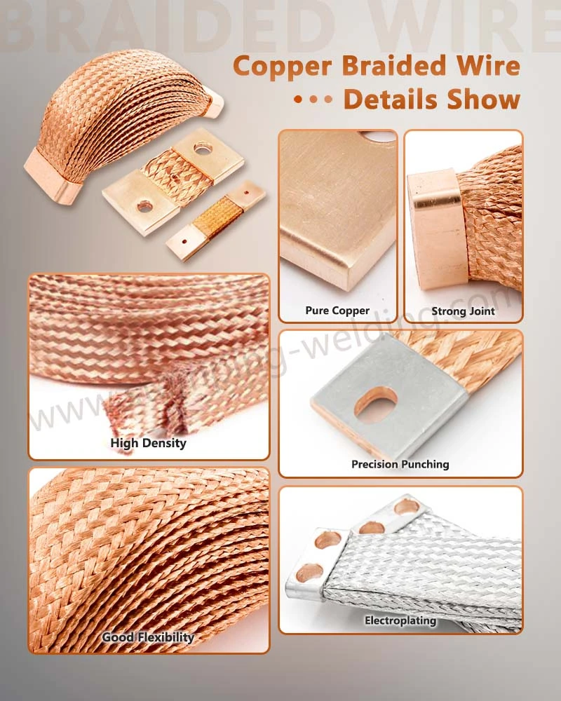
A Flexible Copper Foil Busbar is normally constructed from multiple thin copper sheets stacked together and joined at defined terminal regions. The flexible section remains capable of repeated deformation while the terminal area provides a low-resistance electrical interface.
For high-current applications, the manufacturing process can include:
Copper foil slitting and dimensional preparation.
Multi-layer stacking according to the specified cross-sectional area.
Alignment and fixture positioning.
Molecular diffusion welding or another specified high-integrity joining process at terminal zones.
Deburring and edge conditioning.
Surface cleaning before plating.
Tin, silver, or other specified surface treatment.
Dimensional inspection.
Electrical resistance and temperature-rise verification.
The key engineering distinction is that the flexible section and terminal section do not necessarily require identical mechanical properties.
The flexible section needs controlled deformation. The terminal section needs stable electrical contact and sufficient mechanical strength.
C1100 Copper and 0.01 mm-Class Dimensional Inspection
C1100-grade electrolytic tough-pitch copper is commonly selected where high electrical conductivity is required. Depending on the supplied material specification, pure copper can approach 100% IACS conductivity.
For precision flexible busbar manufacturing, important dimensional controls include:
| Parameter | Typical engineering consideration |
| Copper material | C1100 / equivalent high-conductivity copper |
| Conductivity | Up to approximately 100% IACS |
| Foil thickness | Defined according to current and flexibility requirements |
| Foil width | Determined by current capacity and installation envelope |
| Terminal thickness | Controlled according to joining process and bolt/weld interface |
| Flatness | Controlled to maintain terminal contact |
| Hole position | CNC/CMM or dedicated gauge inspection |
| Critical dimensions | Can be controlled to approximately ±0.01 mm where process capability permits |
| Edge condition | Burr-controlled to prevent insulation or assembly damage |
A CMM inspection program is particularly useful for complex terminal geometry, hole locations, and three-dimensional forming.
1000 A-Class Current Paths and Thermal Design
Current rating cannot be assigned from conductor cross-sectional area alone. The thermal boundary conditions must be considered.
A simplified conductor-loss relationship is:
P = I²R
where P is resistive power loss, I is current, and R is conductor resistance.
As current increases, even a small reduction in resistance becomes significant. For example, reducing connection resistance from 100 μΩ to 50 μΩ at 1000 A changes the theoretical connection loss from:
1000² × 100 μΩ = 100 W
to:
1000² × 50 μΩ = 50 W
This is why terminal joining, plating, contact pressure, and interface cleanliness can be as important as the nominal copper cross-section.
Request Free DFM Evaluation & Quote
Tin and Silver Plating at 3–12 μm for Oxidation Control
Bare copper develops surface oxides during exposure to air and elevated temperature. Surface treatment is therefore selected according to the electrical interface, environmental exposure, and joining method.
For flexible high-current connections, common options include tin plating and silver plating.
| Surface treatment | Typical thickness | Main engineering function | Typical consideration |
| Tin plating | 3–12 μm | Oxidation protection and stable terminal surface | Cost-effective and widely used |
| Silver plating | 3–12 μm | High conductivity and strong electrical interface | Suitable for higher-performance electrical interfaces |
| Bare copper | - | Maximum material simplicity | Requires controlled environmental exposure |
| Nickel barrier + conductive top layer | Application-specific | Diffusion/environmental control | Used when substrate interaction must be controlled |
The actual coating specification should be defined by drawing rather than using a universal thickness.
For production QA, coating thickness can be verified using methods such as X-ray fluorescence (XRF) or metallographic cross-section analysis.
3–12 μm Plating Thickness and Contact Resistance Control
The purpose of plating is not simply visual corrosion protection. The finished surface must maintain a stable electrical interface after assembly and environmental exposure.
Important controls include:
Plating thickness measurement at specified locations.
Surface cleanliness before plating.
Adhesion verification.
Visual inspection for exposed substrate, blistering, and peeling.
Contact-resistance measurement.
Salt-spray or environmental testing when required by the customer specification.
Cross-section analysis for process validation.
For high-current systems, plating selection should also consider the joining method. A surface treatment suitable for a bolted terminal is not automatically suitable for a laser-welded joint.
Laser Welding Cu-Al vs. Resistance Silver Brazing at 0.01 mm-Class Interfaces
When the flexible connection is integrated with copper, aluminum, or dissimilar-metal terminals, joining technology directly affects electrical resistance, mechanical strength, and long-term reliability.
| Joining method | Primary advantage | Main process variable | Suitable application |
| Laser welding Cu-Al | Localized heat input and automated processing | Laser power, focus, speed, beam profile | Cu-Al battery and power-electronics connections |
| Resistance welding | High production efficiency | Current, pressure, weld time | High-volume stamped components |
| Resistance silver brazing | Conductive joint with controlled filler | Current, pressure, temperature, filler | Copper contact and high-current assemblies |
| Molecular diffusion welding | Solid-state metallurgical bonding | Pressure, temperature, surface condition | Laminated copper foil terminals |
| Mechanical bolting | Serviceable connection | Torque, contact pressure, surface condition | Field-serviceable busbars |
For dissimilar-metal joints, laser welding Cu-Al requires particular attention to intermetallic compound formation. Heat input, beam position, and joint geometry must be controlled to prevent excessive brittle intermetallic phases.
For laminated copper foil terminals, molecular diffusion welding can provide a consolidated terminal section while retaining flexibility in the unjoined foil region.
15 kV/mm Dielectric Requirements and Insulation Separation
Electrical isolation must be evaluated separately from conductor flexibility.
Where the flexible busbar is insulated with polymer film, heat-shrink material, or powder coating, the design engineer should define:
Dielectric withstand voltage.
Minimum insulation thickness.
Creepage distance.
Clearance distance.
Operating temperature.
Flame-retardancy requirement.
Chemical exposure.
Mechanical abrasion resistance.
For selected insulation systems, a dielectric strength requirement may exceed 15 kV/mm, but the actual specification depends on polymer type, thickness, test method, and environmental conditions.
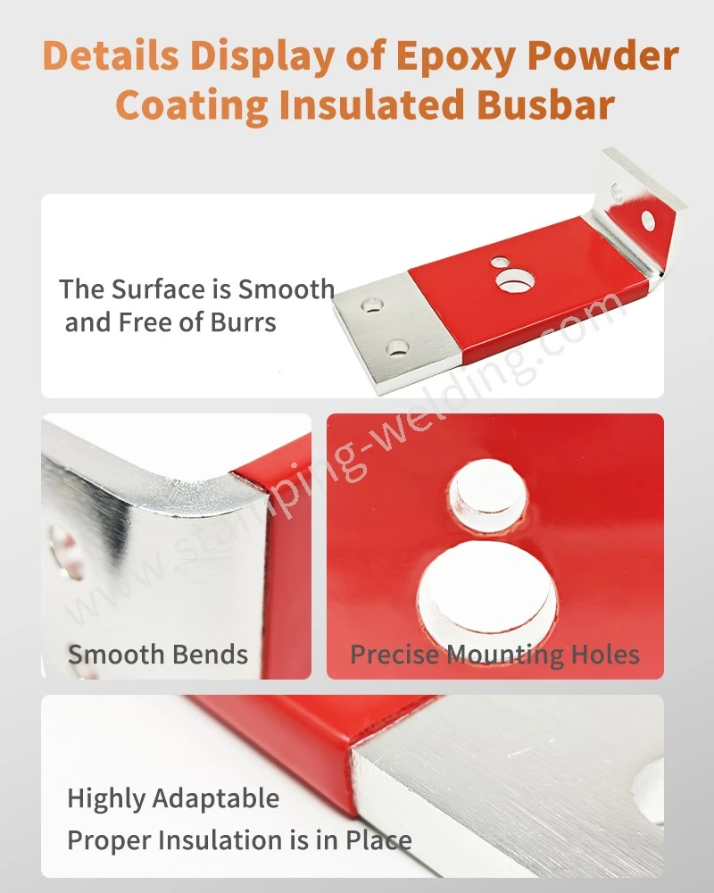
Epoxy Powder Coating vs. Heat-Shrink Insulation at UL 94 V-0
Insulation construction influences assembly size, thermal dissipation, and mechanical durability.
| Characteristic | Epoxy powder coating | Heat-shrink insulation |
| Application | Coating and thermal curing | Tubing installation and shrinking |
| Geometry | Conforms closely to component | Requires sufficient tubing clearance |
| Typical dielectric performance | High when correctly formulated | Depends on polymer grade and thickness |
| UL 94 V-0 availability | Yes, formulation-dependent | Yes, material-dependent |
| Thermal dissipation | Better with a controlled thin coating | Can add thermal resistance |
| Edge coverage | Strong when the process is controlled | Depends on tubing fit |
| Automation | High | Moderate to high |
| Rework | More difficult | Generally easier |
| Complex three-dimensional parts | Suitable with controlled powder process | Tubing limitations |
For EV and ESS applications, UL 94 V-0 is frequently specified where flame-retardant performance is required. Railway applications may additionally require materials evaluated against EN 45545, while environmental management systems can be controlled under ISO 14001.
The insulation specification should always identify the exact material grade, thickness, and applicable test method rather than stating only "insulated."
±0.01 mm Stamping and CMM Inspection for Flexible Connection Terminals
Flexible conductors often connect to stamped terminals, electrical cabinets, battery modules, or machined interfaces. Dimensional accuracy at the terminal determines assembly fit and electrical contact.
A controlled production route can combine:
Copper preparation → Precision stamping → Deburring → Forming → Foil stacking → Molecular diffusion welding → Plating → Insulation → CMM inspection → Electrical testing → Final inspection
For stamped terminal components, process capability should focus on hole diameter, hole-to-edge distance, terminal flatness, bend angle, and mounting position.
IATF 16949 and PPAP Level 3 Quality Documentation
For automotive programs, the quality package may include PPAP Level 3, depending on customer requirements.
Typical documentation can include:
| Quality document | Engineering purpose |
| Process Flow Diagram | Defines manufacturing sequence |
| PFMEA | Identifies process failure modes |
| Control Plan | Defines production controls |
| Dimensional Report | Confirms drawing requirements |
| Material Certificate | Verifies copper grade and specification |
| Plating Report | Confirms coating thickness |
| CMM Report | Verifies three-dimensional geometry |
| Electrical Test Report | Confirms resistance/conductivity |
| Capability Study | Evaluates critical dimensions |
| PPAP Level 3 | Provides production-part approval evidence |
An IATF 16949-certified manufacturing system provides the process-control framework, but individual product acceptance still depends on the customer's drawing, specification, and validation plan.
1000 A-Class Selection Matrix for EV, ESS and Transformer Connections
The selection between braided copper and laminated copper foil should begin with the movement profile.
| Application condition | Flexible braided copper wire | Flexible copper foil busbar | Engineering preference |
| Large multidirectional movement | Excellent | Moderate | Braided structure |
| Repeated axial expansion | Excellent | Excellent | Geometry-dependent |
| Compact EV battery package | Moderate | Excellent | Copper foil structure |
| High-current ESS connection | Excellent | Excellent | Current + thermal design |
| Transformer vibration | Excellent | Good to excellent | Braided structure often advantageous |
| Controlled flat busbar routing | Limited | Excellent | Copper foil busbar |
| Laminated busbar integration | Limited | Excellent | Copper foil structure |
| Automated terminal welding | Good | Excellent | Foil terminal |
| Very flexible grounding connection | Excellent | Limited | Braided structure |
| Controlled insulation coating | Good | Excellent | Foil structure |
| Tight terminal dimensional tolerance | Moderate | Excellent | Foil structure |
| Complex multidirectional installation | Excellent | Moderate | Braided structure |
The table should not be interpreted as a universal product ranking. The correct architecture depends on the system's displacement vector, current waveform, thermal environment, mounting geometry, and qualification requirements.
10 kA Peak Current and Short-Circuit Considerations
Continuous current and short-circuit current are different design conditions.
For a high-current connection, engineers should define at minimum:
Continuous current → peak current → short-circuit current → duration → ambient temperature → allowable temperature rise → conductor resistance → terminal resistance
For systems operating under fault conditions, the electromagnetic force generated by high current can become significant. The flexible joint must therefore withstand both thermal energy and mechanical force.
For example, instantaneous electromagnetic forces increase strongly with current magnitude. A design validated only at the continuous operating current cannot automatically be considered suitable for a short-circuit event.
For fuse-related assemblies, system validation may also reference IEC 60269 where applicable.
100% IACS Conductivity and <10 nH Stray-Inductance Design
For DC and high-frequency power electronics, resistance is not the only electrical parameter.
A laminated busbar can reduce loop area and therefore help reduce parasitic inductance. In suitable inverter and DC-link architectures, designers may target stray inductance below 10 nH.
The final inductance depends on:
Conductor spacing.
Forward and return current path.
Lamination arrangement.
Terminal geometry.
Loop area.
Connection length.
Adjacent magnetic materials.
Switching frequency.
This is one reason a Flexible Copper Foil Busbar can be preferable where a compact, controlled current path is required.
By contrast, a braided copper connection may provide substantially greater mechanical compliance but can have a less controlled electromagnetic geometry unless the conductor routing is specifically engineered.
C1100 Copper vs. C2680 Brass at 100% IACS Electrical Paths
Copper and brass should not be treated as interchangeable conductor materials.
| Property | C1100 copper | C2680 brass |
| Primary role | High-conductivity current path | Structural/contact component |
| Electrical conductivity | Approximately 100% IACS class | Significantly lower than pure copper |
| Thermal conductivity | High | Lower |
| Formability | High | High |
| Typical use | Busbars, flexible conductors, terminals | Stamped brackets, terminals, structural electrical parts |
| Current-path suitability | Excellent | Application-dependent |
| Main selection factor | Conductivity + thermal performance | Strength + formability + cost |
C2680 can be useful where mechanical strength, stamping behavior, and dimensional stability are important. For the primary high-current conductor, high-conductivity copper is normally considered where low electrical resistance is the design priority.
17 × 10⁻⁶/K Thermal Expansion and Joint Geometry Validation
A flexible joint should be validated according to the actual displacement envelope rather than a nominal bending radius alone.
A validation plan can include:
Thermal cycling → dimensional inspection → electrical resistance measurement → vibration testing → mechanical displacement cycling → insulation test → final dimensional inspection
For EV and ESS applications, the test profile should reproduce the actual battery or power-electronics installation conditions as closely as possible.
Critical acceptance criteria can include:
| Validation item | Example engineering parameter |
| Copper conductivity | Up to 100% IACS |
| Dimensional tolerance | Up to ±0.01 mm on selected critical features |
| Plating thickness | 3–12 μm, specification-dependent |
| Dielectric strength | >15 kV/mm where specified |
| Flame rating | UL 94 V-0 where specified |
| Stray inductance | <10 nH where required |
| Quality system | IATF 16949 |
| Automotive submission | PPAP Level 3 where required |
| Environmental management | ISO 14001 |
These values are design targets or specification examples, not universal acceptance limits. The customer's drawing, validation specification, and applicable standards remain controlling.
Download Busbar Design Specification
3–12 μm Plating and PPAP Level 3: What Procurement Should Specify
A purchase specification for flexible copper expansion joints should contain enough information to prevent multiple interpretations between supplier and customer.
At minimum, the RFQ or drawing should define:
Conductor material and temper.
Copper conductivity requirement.
Foil or braid construction.
Finished dimensions.
Critical tolerances.
Minimum bend radius or displacement requirement.
Terminal configuration.
Welding or brazing method.
Plating material and thickness.
Insulation material and thickness.
Dielectric test requirement.
Temperature-rise limit.
Electrical resistance limit.
Environmental test requirements.
PPAP level.
Traceability requirements.
For volume production, the supplier should also provide process capability evidence for critical dimensions rather than relying only on final inspection.
50-Word FAQ: High-Current Flexible Copper Joint Procurement
What is the difference between Flexible Braided Copper Wire and a Flexible Copper Foil Busbar?
Flexible braided copper wire provides multidirectional compliance and is effective for vibration and large displacement. A flexible copper foil busbar provides a flatter, more controlled current path and is better suited to compact EV, ESS, and power-electronics assemblies requiring defined geometry.
What plating thickness should be specified for a flexible copper expansion joint?
A typical engineering specification may define 3–12 μm tin or silver plating, but the correct value depends on the electrical interface, environment, joining method, and customer qualification requirements. Plating thickness should be verified by XRF or metallographic cross-section testing.
Can a Shunt Expansion Joint Manufacturer provide PPAP Level 3 documentation?
Yes. For automotive programs, PPAP Level 3 can include the process flow, PFMEA, control plan, dimensional results, material certificates, capability studies, and validation records. The exact submission package should follow the customer's PPAP manual and purchase specification.
contact us