Grounding and Power Distribution Busbars in Rail Transit & Traction Substations
Oct 02, 2026
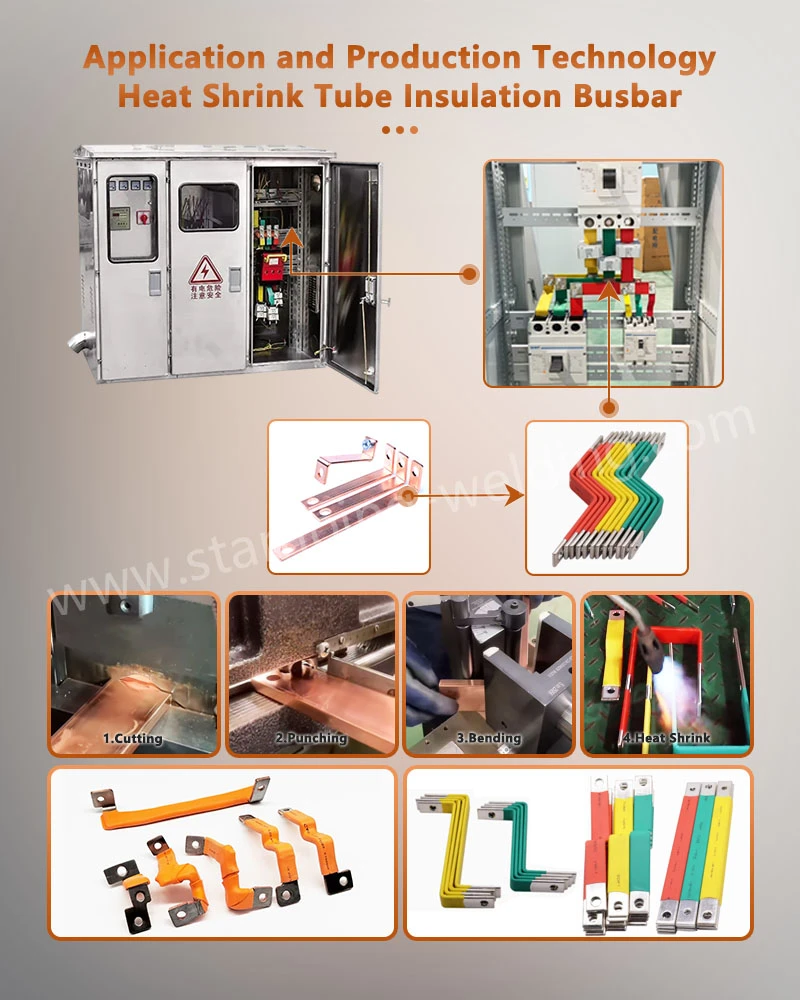
For 750V and 1500V DC rail traction systems, the busbar must control fault-current paths, thermal rise, mechanical forces, and insulation clearance at the same time. A Rail Transit Grounding Busbar is not simply a copper strip: its cross-section, joint resistance, mounting geometry, surface treatment, and insulating system must be matched to the traction return and grounding architecture defined for the installation. EN 50122-1 addresses electrical safety, earthing, and the return circuit for fixed railway installations, while EN 50122-2 addresses stray-current effects in DC traction systems.
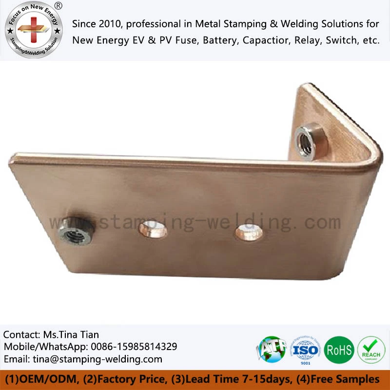
750V/1500V DC Rail Grounding Busbar Design to EN 50122-1
A traction substation distributes DC power through high-current conductors while providing controlled paths for protective bonding and fault current. The grounding and power distribution busbars therefore have different electrical functions even when they are manufactured from similar copper grades.
For a Rail Transit Grounding Busbar, the design review should begin with the complete current path rather than the nominal system voltage. The engineer should define:
750V or 1500V DC system voltage and the applicable insulation coordination.
Continuous operating current, including ambient-temperature derating.
Prospective short-circuit current, fault duration, and protective-device clearing time.
Copper cross-section, busbar spacing, and parallel-conductor configuration.
Joint resistance, bolt preload, and contact-surface condition.
Grounding and bonding topology according to the traction installation design.
Creepage and clearance distances at the maximum operating voltage.
Mechanical support spacing against electrodynamic forces during short circuits.
Corrosion protection for copper, plated interfaces, and mounting hardware.
EN 50122-1 specifically covers electrical safety, earthing, and the return circuit for fixed railway installations. For DC traction systems, stray-current control also requires consideration under EN 50122-2.
C1100 Copper at 100% IACS and Low-Resistance Joints
For high-current traction applications, C1100 pure copper is frequently selected where electrical conductivity and thermal performance dominate the material decision. A commonly specified conductivity target for high-conductivity copper is 100% IACS.
The actual busbar temperature, however, is not determined by conductivity alone. Joint resistance, contact pressure, surface condition, conductor geometry, and heat dissipation can become the dominant variables.
| Design variable | Engineering consideration | Typical production control |
| C1100 copper | High electrical conductivity | Material certificate and grade verification |
| Cross-sectional area | Determines current density and thermal rise | Drawing-controlled dimensions |
| Joint resistance | Influences localized heating | Contact-resistance inspection |
| Busbar flatness | Affects support and joint contact | Flatness measurement |
| Hole position | Controls assembly alignment | CMM / optical inspection |
| Surface treatment | Controls corrosion and interface stability | Coating/plating thickness inspection |
| Edge condition | Prevents insulation damage | Deburring and visual inspection |
For large copper bars, a small dimensional error can accumulate across several connection points. Hole pitch, bend angle, slot width and mounting reference points should therefore be controlled from the same datum system.
Short-Circuit Mechanical Forces at 25–50 kA Fault Levels
A busbar can satisfy its continuous-current requirement and still fail during a short circuit. The electromagnetic force between parallel conductors increases rapidly with fault current, making support spacing, conductor orientation, and fastener strength part of the electrical design.
For a simplified parallel-conductor arrangement, electromagnetic force is approximately proportional to the product of the instantaneous currents:
where I represents current and d represents conductor spacing.
The actual short-circuit design must use the system-specific prospective fault current, waveform, conductor geometry and protection clearing time. A 25 kA fault and a 50 kA fault cannot be treated as a simple two-times mechanical design problem because the peak asymmetrical current can exceed the RMS short-circuit value.
For this reason, the busbar drawing should define:
Support spacing in mm.
Copper thickness and width in mm.
Short-circuit current in kA RMS.
Peak withstand current where specified.
Fault duration in ms.
Fastener grade and tightening torque.
Insulating support material and mechanical rating.
Minimum conductor-to-conductor and conductor-to-ground clearance.
Resistance Welding, Brazing and Mechanical Joints at 750V/1500V DC
The connection technology determines local resistance and thermal distribution.
| Joining method | Main application | Engineering control | Main risk |
| Bolted joint | Removable substation connections | Torque and contact pressure | Joint resistance increase |
| Resistance welding | Repetitive copper component joining | Current, force, and weld time | Heat-affected deformation |
| Resistance silver brazing | Copper/contact assembly | Brazing temperature and filler control | Incomplete wetting |
| Laser welding | Compact Cu-to-Cu or Cu-Al assemblies | Beam power, speed, and focal position | Porosity/penetration variation |
| Molecular diffusion welding | High-integrity laminated interfaces | Pressure, temperature, and surface preparation | Interface contamination |
For copper busbars, the joint should be evaluated as an electrical interface rather than simply as a mechanical connection. Contact resistance mapping, thermal imaging under representative current and metallographic examination can identify localized heating that may not be visible during dimensional inspection.
Request Free DFM Evaluation & Quote
25–50 kA Short-Circuit Withstand and C1100 Busbar Geometry
The critical design parameter for a traction busbar is not simply its nominal ampacity. A production drawing must define how the conductor behaves during both normal operation and a fault event.
25–50 kA Fault Current and Electrodynamic Load
During a short circuit, adjacent conductors experience attractive or repulsive electromagnetic forces depending on current direction. These forces transfer directly into the insulating supports, mounting bolts, and copper bends.
A practical busbar design review should therefore examine the entire load chain:
Copper conductor → connection point → fastener → insulating support → cabinet/substation structure
If the support system is too flexible, the copper may move sufficiently to reduce insulation clearance. If the busbar is rigidly constrained without appropriate stress relief, thermal expansion can transfer excessive force into connection points.
For high-current assemblies, the following dimensional characteristics should be controlled:
| Parameter | Example engineering control |
| Copper thickness | Drawing-specific, typically mm-level control |
| Busbar width | Drawing-specific |
| Hole diameter | ±0.05 mm or drawing requirement |
| Hole pitch | ±0.05–0.10 mm depending on assembly |
| Bend angle | ±1° or drawing requirement |
| Flatness | Drawing-specific |
| Burr height | Controlled after stamping |
| Plating thickness | Specification-dependent |
| Joint resistance | Project-specific acceptance value |
The values above are production-control examples rather than universal railway acceptance limits. The final specification must follow the traction-system calculation and customer drawing.
C1100 vs C2680 at 100% IACS Conductivity and High-Strength Interfaces
Material selection should follow the electrical and mechanical function of each component.
| Property | C1100 Pure Copper | C2680 Brass |
| Electrical conductivity | High; commonly specified up to 100% IACS | Significantly lower than pure copper |
| Primary advantage | Current carrying and thermal conduction | Mechanical strength and formability |
| Typical busbar role | Main power conductor | Hardware / formed auxiliary component |
| Resistance heating | Lower for equivalent cross-section | Higher |
| Stamping behavior | Requires process control for thick sections | Generally favorable |
| High-current distribution | Preferred where low resistance dominates | Usually not the first choice |
| Surface treatment | Tin/nickel/silver depending on interface | Tin/nickel/other specified finish |
A C1100 busbar can be mechanically stamped, CNC machined, bent, drilled or laser processed. For high-volume production, progressive stamping and automated forming can reduce dimensional variation when the geometry is suitable for a die-based process.
Progressive Stamping and CMM Inspection at ±0.01 mm
Complex grounding and power-distribution busbars may combine:
Piercing holes.
Notches and slots.
Formed bends.
Embossed features.
Contact fingers.
Mounting references.
Surface-treatment zones.
For repetitive geometries, progressive die stamping can integrate piercing and forming operations. Critical features should then be verified using CMM inspection or dedicated gauges.
A ±0.01 mm tolerance should only be specified where the functional interface requires it. Applying ultra-tight tolerances to every feature increases tooling cost without necessarily improving electrical performance.
The inspection plan should classify dimensions into:
CTQ dimensions - directly affecting electrical or mechanical assembly.
Interface dimensions - mating with terminals, insulators, or fasteners.
Reference dimensions - controlling downstream assembly.
Non-functional dimensions - controlled to drawing but not requiring excessive precision.
This approach aligns manufacturing inspection with actual assembly risk.
EN 45545-2:2020+A1:2023 and Dielectric Insulation Above 15 kV/mm
For railway applications, insulation selection cannot be separated from fire performance. The current BSI listing identifies BS EN 45545-2:2020+A1:2023 as the current release for fire behaviour requirements of materials and components used on railway vehicles. The standard establishes reaction-to-fire requirements according to applicable hazard levels and requirement sets.
For electrical cabinets, traction equipment and insulated busbar assemblies, the specification may combine:
Flame-retardant insulation.
Low smoke performance.
Halogen-free material requirements where specified.
Dielectric strength.
Creepage distance.
Clearance distance.
Temperature resistance.
Tracking resistance.
Mechanical retention.
The phrase "halogen-free" should not be treated as equivalent to EN 45545 compliance. EN 45545-2 is a classification and test framework, and the applicable requirement set depends on the railway application, vehicle category, and hazard level.
UL 94 V-0 and EN 45545 Fire-Performance Evaluation
UL 94 V-0 and EN 45545-2 address different compliance frameworks. A material with a UL 94 V-0 classification should not automatically be represented as EN 45545 compliant.
| Requirement | UL 94 V-0 | EN 45545-2 |
| Primary scope | Plastics flammability classification | Railway vehicle fire behaviour |
| Application | Material-level flammability | Railway-specific material/component requirements |
| Smoke evaluation | Not equivalent to railway classification | Included within applicable requirements |
| Toxicity | Not a direct substitute | Relevant to applicable requirement sets |
| Railway hazard level | Not defined | Defined through EN 45545 framework |
| Procurement use | Material screening | Railway compliance specification |
For a traction busbar assembly, the insulation specification should therefore identify the exact material, thickness, application, test report, and applicable EN 45545 requirement set instead of relying on a generic "flame-retardant" description.
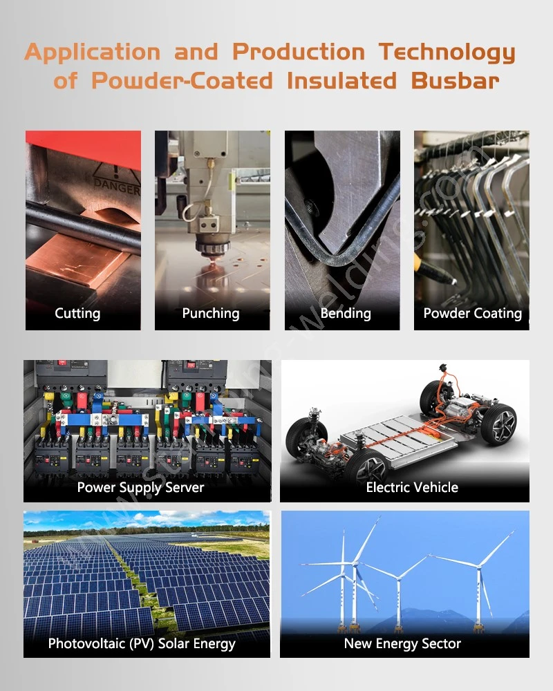
Epoxy Powder Coating and >15 kV/mm Dielectric Strength
Epoxy powder coating can provide a durable insulating layer on metal components when coating thickness, surface preparation and curing are controlled.
The relevant engineering variables include:
Coating thickness in µm.
Substrate cleanliness.
Surface roughness.
Cure temperature.
Cure time.
Adhesion.
Dielectric breakdown strength.
Edge coverage.
Pinholes and exposed metal.
Long-term thermal cycling.
A specified dielectric breakdown value such as >15 kV/mm should be treated as a material or system specification that must be verified under the applicable test method. It should not be presented as a universal EN 45545 requirement.
750V/1500V DC Pre-Drilled Busbars and Insulating Supports
Pre-drilled busbars reduce installation work and provide repeatable connection locations for traction cabinets, DC switchgear, and power distribution assemblies. The hole pattern should be designed together with the insulating support geometry rather than added after the conductor design is complete.
Pre-Drilled C1100 Busbar Geometry and ±0.05 mm Hole Position
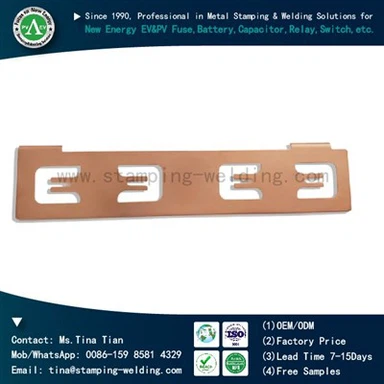
A pre-drilled Traction Substation Copper Bar normally includes mounting holes, terminal holes, slots, or connection apertures.
The critical relationship is:
Hole pattern → support position → terminal position → enclosure datum
If these four references are not controlled from the same datum system, installation tolerances can accumulate.
For automated or semi-automated assembly, hole position can be controlled by:
Progressive stamping die.
CNC punching.
Laser cutting.
CNC machining.
Dedicated drilling fixture.
CMM inspection is appropriate for first-article verification of complex three-dimensional busbars, particularly where bends change the spatial position of mounting holes.
Insulating Supports at 1500V DC and Controlled Clearance
Insulating supports perform three functions:
Maintain conductor position.
Resist electrodynamic movement during faults.
Maintain electrical separation under normal and abnormal conditions.
For a 1500V DC assembly, the required clearance and creepage distances cannot be assigned from voltage alone. They depend on the insulation system, pollution conditions, material characteristics, altitude, overvoltage category, and applicable railway/electrical standards.
The drawing should therefore define the required minimum distances rather than allowing the supplier to select them arbitrarily.
Metro Power Interconnect Assembly With Integrated Mounting Features
A Metro Power Interconnect Assembly can combine:
C1100 copper busbar.
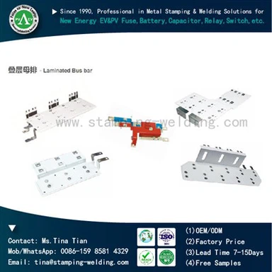
Laminated busbar sections.
Tin-plated or nickel-plated interfaces.
Insulating supports.
Pre-drilled mounting holes.
Bolted terminals.
Laser-welded subcomponents.
Epoxy powder insulation.
Identification marks.
For high-volume rail equipment, integrating these features into one controlled assembly can reduce the number of loose components and improve installation repeatability.
Request Free DFM Evaluation & Quote

IATF 16949, PPAP Level 3 and CMM Quality Control for Rail Busbars
Although railway projects are not automatically governed by IATF 16949, an automotive-grade manufacturing control system can provide a useful framework for process discipline, traceability, and dimensional control when the supplier also serves EV and industrial customers.
For a production Rail Transit Grounding Busbar, the quality package can include:
Material certificate.
RoHS / REACH documentation where specified.
First Article Inspection.
CMM dimensional report.
Plating thickness report.
Electrical resistance measurement.
Coating thickness measurement.
Dielectric withstand test.
Adhesion test for powder coating.
Welding parameter records.
Metallographic cross-section for welded joints.
PPAP Level 3 documentation where contractually required.
CMM ±0.01 mm Inspection and CTQ Traceability
Critical-to-quality characteristics should be connected directly to the inspection plan.
| CTQ | Measurement method | Typical control purpose |
| Hole position | CMM / optical system | Assembly alignment |
| Thickness | Micrometer/thickness gauge | Current capacity and fit |
| Flatness | CMM / surface plate | Support contact |
| Bend angle | CMM / angle gauge | Cabinet clearance |
| Plating thickness | XRF | Corrosion/contact interface |
| Contact resistance | Four-wire measurement | Electrical loss |
| Coating thickness | Eddy-current gauge | Insulation consistency |
| Dielectric withstand | Hi-pot tester | Electrical insulation |
| Weld penetration | Metallography/sectioning | Joint integrity |
For high-current connections, electrical inspection should not be replaced by dimensional inspection. A busbar can meet every drawing dimension and still exhibit excessive interface resistance.
PPAP Level 3 Documentation for OEM Production
Where a customer requires PPAP Level 3, the submission may include:
Design records.
Engineering change documentation.
Process flow diagram.
PFMEA.
Control plan.
MSA studies where applicable.
Dimensional results.
Material and performance test results.
Initial process capability data.
Qualified laboratory documentation.
Sample production parts.
Part Submission Warrant.
The exact submission content should follow the customer's PPAP manual and contractual requirements.
C1100 Busbar Manufacturing From T1 Prototype to 15–20 Day Mass Production
A practical development sequence for custom busbars is:
2D/3D drawing review → DFM analysis → material confirmation → prototype/T1 sample → dimensional validation → electrical testing → tooling release → pilot production → PPAP → mass production
For a stamped busbar, the DFM review should identify:
Minimum bend radius.
Grain direction where applicable.
Burr direction.
Piercing sequence.
Tool access.
Scrap ratio.
Forming interference.
Plating requirements.
Post-processing deformation.
For welded assemblies, the review should additionally identify weld access, heat input, clamping method, joint overlap, surface condition and inspection method.
The objective is not simply to produce a copper bar. It is to establish a repeatable manufacturing process in which the electrical, mechanical and insulation characteristics remain within the agreed specification from T1 samples through serial production.
ISO 14001 and Controlled Copper Manufacturing
Copper processing also requires control of material utilization, chemical treatment, wastewater, coating processes and production waste.
Where an environmental management system is required, ISO 14001 can provide the management framework for these manufacturing activities.
For procurement teams, environmental documentation should be separated from product-performance evidence. ISO 14001 certification does not itself prove copper conductivity, dielectric strength, or railway fire classification.
Engineering Specification Checklist for 750V/1500V DC Traction Busbars
Before releasing a purchase order for a Rail Transit Grounding Busbar or Traction Substation Copper Bar, the engineering package should define:
System voltage: 750V DC / 1500V DC.
Continuous current: A.
Prospective short-circuit current: kA RMS.
Peak short-circuit current: kA, where applicable.
Fault duration: ms.
Copper grade: C1100 / specified equivalent.
Conductivity: target such as 100% IACS, where applicable.
Cross-section: width × thickness.
Hole pattern: datum-controlled.
Bend geometry: angle and radius.
Surface treatment: tin/nickel/silver/bare copper.
Insulation: epoxy powder / molded insulation / other specified system.
Dielectric requirement: project-specific, with test method.
Fire requirement: applicable EN 45545 requirement set.
Creepage and clearance: calculated project values.
Support spacing: based on short-circuit mechanical loading.
Inspection: CMM, electrical resistance, coating and dielectric tests.
Documentation: FAI / PPAP Level 3 where required.
Traceability: material lot, production batch, and inspection records.
The most reliable procurement specification connects each requirement to a measurable characteristic, an inspection method and an acceptance criterion. This prevents terms such as "high conductivity," "fire resistant," or "heavy-duty" from replacing engineering limits.
FAQ: PPAP Level 3, T1 Samples and Busbar Plating Thickness
What documents are normally required for PPAP Level 3 traction busbar production?
PPAP Level 3 normally requires design records, process flow, PFMEA, control plan, dimensional results, material/performance test records, MSA where applicable, sample parts, and PSW. Customer-specific PPAP requirements take precedence.
How long does a T1 prototype take for a custom C1100 copper busbar?
T1 timing depends on geometry, tooling requirements, and surface treatment. Simple laser-cut or CNC prototypes can be produced without a progressive die, while complex stamped busbars require tooling development before representative T1 parts are available.
How is copper busbar plating thickness verified during production?
Tin, nickel, or silver plating thickness can be checked using XRF or another validated coating-thickness method. Measurement locations should include functional contact areas and representative production surfaces, with acceptance limits defined on the drawing or purchase specification.
contact us