Copper Busbar Production Processes And Advances in Continuous Extrusion Technology: An Analysis Of The Manufacturing Of Ultra-thin Copper Busbars And Hollow-section Conductive Busbars
Oct 06, 2026
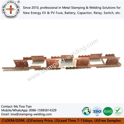
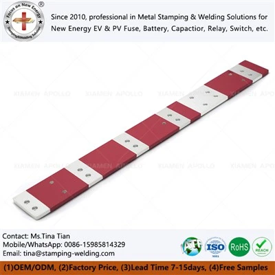
Copper busbars are vital conductive materials used for high-current transmission in power equipment, finding primary application in high- and low-voltage electrical appliances, power distribution systems, switchgear, busway systems, and electrolytic equipment. Compared to standard conductors, copper busbars feature larger cross-sectional areas and lower electrical resistance, enabling them to handle high current loads within limited spaces while offering excellent machinability. Consequently, factors such as material temper, cross-sectional dimensions, surface quality, and electrical conductivity directly impact the reliability of electrical connections in end-use equipment.
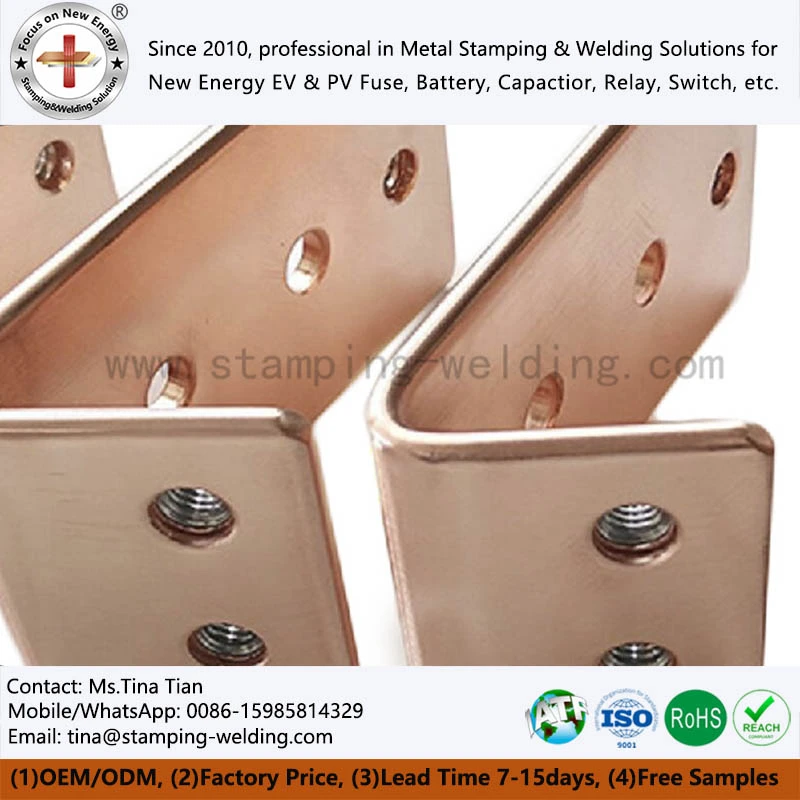
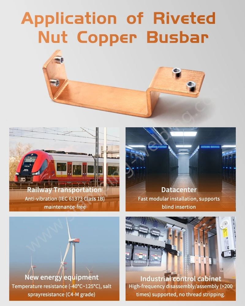
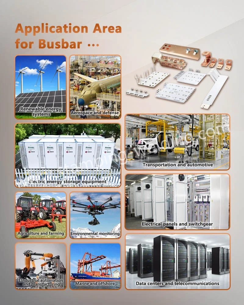
In terms of product form, copper busbars typically feature a rectangular cross-section with rounded corners, though designs may also incorporate irregular, stepped, or hollow profiles depending on equipment structure. Driven by the growing demand for high-power-density power distribution systems in sectors such as new energy vehicles, energy storage, power electronics, rail transit, and data centers, copper busbar manufacturing is evolving from traditional large-scale processing toward high dimensional precision, continuous production, ultra-thin profiles, and complex cross-section forming.
Main Categories of Copper Busbar Production Processes
Traditional copper busbar manufacturing primarily employs rolling and extrusion processes. These methods differ significantly regarding billet preparation, microstructural control, material utilization rates, equipment investment, and achievable dimensional ranges. For standard electrical copper busbars, the choice of process is typically determined by a combination of factors, including product thickness, width, length, conductivity, mechanical properties, and downstream processing requirements.
One well-established production route involves hot-rolling large ingots into coils, followed by high-precision cold rolling. In this process, copper billets undergo melting, casting, and hot rolling to form coils, which are then gradually reduced to the target thickness via cold rolling. While hot rolling effectively refines the as-cast microstructure-resulting in greater internal uniformity-the process involves extensive equipment and multiple stages, placing high demands on facility infrastructure, rolling mills, and heat treatment equipment.
An alternative route combines horizontal continuous casting or upward continuous casting (producing coils) with high-precision cold rolling. This method can shorten the production workflow and reduce the need for large-scale hot-rolling equipment, although some as-cast microstructural characteristics may persist within the continuously cast billet. To improve surface and internal quality, some products require treatments such as face milling, which impacts material utilization rates.
For copper ground busbars used in standard power distribution equipment, the material must balance electrical conductivity, mechanical strength, and machinability. In contrast, high-density distribution systems require stricter control over dimensional tolerances, flatness, and surface conditions to meet the installation requirements of compact connection structures.
Continuous extrusion has emerged as a key manufacturing process for copper busbars
Continuous extrusion involves feeding copper billets continuously into the extrusion equipment; frictional heat brings the material to a state suitable for plastic deformation, allowing for continuous shaping within the die cavity. Compared to traditional hot extrusion-which requires separate billet heating-continuous extrusion eliminates certain heating stages and shortens the production workflow through its continuous forming process.
In the manufacture of continuous conductive products like distribution busbars, the advantages of continuous extrusion are evident in material utilization, production continuity, and product length. Using continuously cast copper rods or wire rods as feedstock minimizes the extrusion butt (scrap) typically generated in traditional extrusion processes, resulting in higher material utilization. Furthermore, continuous production reduces fluctuations caused by intermediate shutdowns and material changes.
Continuous extrusion is also well-suited for manufacturing long copper products. While traditional busbar processing is often constrained by equipment length, process sequencing, and handling methods, continuous extrusion enables the production of coiled products spanning thousands of meters or more. For products requiring continuous feeding or subsequent continuous rolling, this method reduces the need for intermediate cutting and joints, while also facilitating transport and downstream processing.
Regarding copper busbars, continuous extrusion is not limited to rectangular cross-sections; through specific die design, it can produce conductive materials with custom cross-sectional shapes, thereby reducing the amount of subsequent machining required.
Impact of the continuous extrusion process on material microstructure and energy consumption
During continuous extrusion, the material undergoes plastic deformation driven by high pressure and friction, with the heat generated by this deformation facilitating the forming process. Compared to some traditional processes, this method involves fewer steps and a higher degree of continuity, thereby reducing energy consumption associated with intermediate handling and repeated reheating.
In terms of microstructure, proper control of extrusion temperature, speed, and die parameters allows the copper material to develop a relatively uniform recrystallized structure. The material typically exhibits excellent surface quality after continuous extrusion, providing a solid foundation for subsequent rolling, drawing, and finishing operations.
Extruded pure copper is generally in a relatively soft state with good plasticity, making it suitable for further processing involving significant deformation, such as rolling. For products like solid copper busbars that require precise control over thickness and cross-sectional dimensions, this material state facilitates the achievement of dimensional precision during subsequent rolling stages.
Technical Challenges in the Continuous Extrusion of Wide Copper Busbars
While continuous extrusion offers advantages such as a streamlined process and high efficiency, increasing the product width complicates the metal flow dynamics within the die cavity. For wide copper busbars, ensuring complete cavity filling and maintaining relatively uniform material flow velocities across different zones are critical factors affecting cross-sectional accuracy and microstructural consistency.
Improper die cavity design can lead to issues such as localized under-filling, dimensional deviations at the edges, or uneven flow velocities during extrusion. Excessive variations in flow velocity can also result in non-uniform internal microstructure and mechanical properties.
Consequently, the continuous extrusion of wide copper busbars requires coordinated control across multiple parameters, including feedstock condition, preheating conditions, die structure, extruder power, and cooling methods. Factors such as the die cavity entry angle, bearing length, and material flow channel design all influence the quality of the final product.
For electrical connection products with specific polarity and mounting orientations-such as positive and negative busbars-dimensional consistency regarding length, width, thickness, hole positioning, and bending zones is crucial alongside electrical conductivity. This ensures precise integration with insulation structures, terminals, and other electrical components.
Rolling and Precision Processing Following Continuous Extrusion
Continuous extrusion does not mean that all copper busbar products can immediately achieve their final dimensions. For ultra-thin busbars and products requiring high thickness precision, further processing-typically rolling-is required after extrusion to reduce thickness and improve dimensional accuracy.
A typical production route for ultra-thin copper busbars may involve upward casting, continuous extrusion, rolling, annealing, and drawing. The specific combination of processes is determined based on the raw material state, target thickness and width, and required final mechanical properties.
Among these steps, rolling primarily handles thickness reduction and cross-sectional precision control; annealing eliminates work hardening, restores material ductility, and establishes a stable microstructure for subsequent processing; and drawing further refines cross-sectional dimensions and surface quality.
For electrical busbar products, if the end application requires punching, bending, welding, or surface treatment, the material's temper (hardness state) must be compatible with these subsequent processes. A material state that is too hard may increase the risk of cracking during forming, while a state that is too soft could compromise the strength of the final assembly; therefore, control is achieved through appropriate work-hardening and annealing protocols.
Thickness and Dimensional Control in Ultra-Thin Copper Busbar Manufacturing
As trends toward miniaturization and high power density in power distribution equipment evolve, busbar thickness has become a critical parameter in structural design. Manufacturing ultra-thin busbars is not merely a matter of reducing material thickness; it requires maintaining the conductive cross-sectional area, mechanical strength, flatness, and dimensional tolerances throughout the thinning process.
In low-voltage power distribution systems, busbars must meet stringent dimensional consistency requirements to ensure precise mating with insulation components, connection terminals, and mounting structures. For thin busbars, factors such as rolling tension, roll gap, rolling speed, and material temperature can all influence the final thickness.
When products are used in high-voltage, high-current systems, factors such as insulation clearance, electric field distribution, mechanical support, and temperature rise must also be comprehensively considered. Consequently, simply pursuing thinner material does not automatically yield superior system performance; the optimal cross-section must be determined based on the rated current and insulation structure.
Manufacturing of Hollow-Section Copper Busbars
In addition to conventional rectangular busbars, hollow-section conductive busbars are increasingly being used in electronics, power systems, and high-power equipment. Hollow structures reduce material weight while maintaining necessary mechanical strength; furthermore, the internal void space can be utilized for heat dissipation or structural integration.
Traditional methods involving the piercing and extrusion of hollow billets are suitable for some simple hollow-section products; however, manufacturing becomes significantly more difficult for complex profiles-particularly those with thin walls, small apertures, or great lengths. Conventional drawing methods are better suited for tubing with uniform wall thickness; processing complex profiles with varying wall thicknesses via this method entails higher difficulty and cost.
In recent years, the manufacturing of hollow copper busbars has shifted toward continuous extrusion and complex cavity forming. Through optimized die design, it is possible to continuously form complex cross-sections while reducing the need for subsequent machining.
For applications involving specific equipment-such as busbars for ABB or Weidmüller-the cross-section, mounting hole locations, end configurations, and insulation interfaces must be designed to match actual equipment connections. Consequently, the ability to produce customized cross-sections and perform precision post-processing has become a crucial aspect of busbar manufacturing.
Die and Cooling Control in Copper Busbar Manufacturing
The stable operation of continuous extrusion depends heavily on die materials, die structure, and cooling conditions. The die not only determines the final cross-sectional shape but also plays a vital role in controlling metal flow and forming pressure.
For wide or complex-section products, significant heat generation and stress concentration can occur in specific areas of the die. Inadequate cooling system design can lead to temperature fluctuations in the die, which in turn affect material flow rates and product dimensions. Therefore, die materials must possess sufficient wear resistance, thermal stability, and resistance to deformation.
In actual production, process parameters must be adjusted based on the copper grade, billet dimensions, extrusion speed, and target cross-section. Stable temperature and speed control help minimize dimensional variations along the length of the product, ensuring greater stability during subsequent rolling and finishing operations.
Aligning Busbar Production Processes with Electrical Applications
Different copper busbar products require distinct manufacturing process routes. Standard power distribution connectors prioritize electrical conductivity, dimensional accuracy, and mechanical strength; high-frequency power electronics focus more on structural compactness, AC losses, and parasitic parameters; while high-current systems require a focus on cross-sectional area, temperature rise, and connection interfaces.
AC busbars typically require consideration of current distribution and temperature rise characteristics based on AC operating conditions, whereas DC systems focus more on continuous current-carrying capacity and contact resistance at connection points. For connection structures requiring high mechanical strength, factors such as the copper material's temper, bending radius, and installation stresses must also be comprehensively considered.
In practical projects, copper busbars intended for equipment such as Siemens units usually require specific structural designs based on equipment interfaces, installation dimensions, and electrical parameters, rather than simple selection based on generic busbar specifications.
Post-Processing and Quality Control of Copper Busbars
After extrusion, rolling, or drawing, copper busbars may undergo additional processes such as punching, cutting, bending, chamfering, welding, and surface treatment. Different processing methods alter the material's local stress state; therefore, the processing sequence must be controlled to prevent cracking or dimensional deviations caused by repeated deformation.
For products requiring tin plating, nickel plating, or other surface treatments, the cleanliness achieved during pre-treatment directly affects the quality of the coating bond. For busbars tasked with carrying high currents, maintaining a high-quality surface in connection areas is crucial to minimizing contact resistance and controlling operating temperature rise.
Furthermore, final product inspections typically cover appearance, dimensions, flatness, straightness, electrical conductivity, and mechanical properties. For customized products, specific inspections regarding hole spacing, bending angles, end configurations, and assembly dimensions are conducted in accordance with engineering drawings.
Development Trends in Continuous Extrusion Technology
In terms of manufacturing technology evolution, copper busbar production is moving toward continuous processing, high precision, high material utilization, and the forming of complex cross-sections. Continuous extrusion eliminates certain intermediate steps found in traditional production workflows and is suitable for manufacturing long busbars, ultra-thin busbars, and products with specialized cross-sectional shapes.
In the future, driven by advancements in new energy, power electronics, data centers, and intelligent power distribution systems, requirements for copper busbar products regarding dimensional accuracy, current-carrying capacity, heat dissipation, and structural integration will become increasingly stringent. Production equipment will increasingly incorporate inline measurement, automatic temperature control, process data acquisition, and intelligent defect detection to enhance stability during continuous production.
Simultaneously, material utilization rates and energy consumption will emerge as critical metrics for process evaluation. Optimizing billet specifications, die structures, rolling schedules, and heat treatment parameters can further minimize machining allowances and material waste, thereby boosting overall production efficiency.
For products requiring custom cross-sections, specific hole configurations, or complex bending geometries, the manufacturing model will rely more heavily on upfront engineering design. Comprehensive evaluation of materials, cross-sections, current ratings, temperature rise, and installation space during the design phase helps mitigate the need for subsequent process adjustments and assembly issues.
Conclusion
Copper busbar manufacturing has evolved from simple material processing into a comprehensive technological system encompassing casting, continuous extrusion, rolling, annealing, drawing, precision forming, and quality inspection. Continuous extrusion is particularly well-suited for producing long busbars with high material utilization and certain complex cross-sections; conversely, the production of ultra-thin and hollow-section busbars requires a combination of rolling, advanced die design, and precision machining technologies to meet the demands of modern electrical equipment for high conductivity, high reliability, and compact design.
From an engineering procurement perspective, busbar selection should extend beyond material grades and purchase prices. It requires a holistic assessment of manufacturing processes and product consistency, taking into account target current, cross-sectional dimensions, processing methods, surface treatments, insulation structures, and end-equipment interfaces.
contact us